
Manual

1336 FORCE™ To PowerFlex® 700S Phase II AC Drive Conversion Guide
25
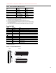
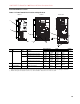
Power Terminal Block Locations
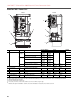
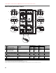
Frames 1 - 4 Power Terminal Block Locations and Specifications
No. Name Frame Description
Wire Size Range
(1)
(1)
Maximum/minimum sizes that the terminal block will accept - these are not recommendations.
Torque Terminal
Bolt Size
(2)
(2)
Apply counter torque to the nut on the other side of terminations when tightening or loosening the terminal bolt in order to avoid damage to the terminal.
Maximum Minimum Maximum Recommended
1 Power Terminal Block 1 Input power and motor connections 4.0 mm
2
(10 AWG)
0.5 mm
2
(22 AWG)
1.7 N-m
(15 lb.-in.)
0.8 N-m
(7 lb.-in.)
—
2 Input power and motor connections 10.0 mm
2
(6 AWG)
0.8 mm
2
(18 AWG)
1.7 N-m
(15 lb.-in.)
1.4 N-m
(12 lb.-in.)
—
3 Input power and motor connections 25.0 mm
2
(3 AWG)
2.5 mm
2
(14 AWG)
3.6 N-m
(32 lb.-in.)
1.8 N-m
(16 lb.-in.)
—
BR1, BR2 10.0 mm
2
(6 AWG)
0.8 mm
2
(18 AWG)
1.7 N-m
(15 lb.-in.)
1.4 N-m
(12 lb.-in.)
—
4 Input power and motor connections 35.0 mm
2
(1/0 AWG)
10 mm
2
(8 AWG)
4.0 N-m
(24 lb.-in.)
4.0 N-m
(24 lb.-in.)
—
2 SHLD Terminal 1-4 Terminating point for wiring shields — — 1.6 N-m
(14 lb.-in.)
1.6 N-m
(14 lb.-in.)
—
3 AUX Terminal Block 1-4 Auxiliary Control Voltage
(3)
PS+, PS-
(3)
External control power: UL Installation - 300V DC, ±10%, Non UL Installation - 270-600V DC, ±10%. Frame 1-6, 100 W
1.5 mm
2
(16 AWG)
0.2 mm
2
(24 AWG)
—— —
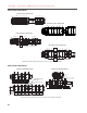
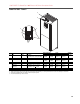
Frame 2
Frames 3 & 4
Frame 1
BR1
BR2
DC+
DC–
PE
U/T1
V/T2
W/T3
R/L1
S/L2
T/L3
Use 75C Wire Only
#10-#14 AWG
Torque to 7 in-lbs
!
DANGER
BR1 B
SHLD SHLD
V/T2 W/T3 PE R/L1 S/L2 T/L3
AUX IN+ AUX OUT–
Optional
Communications
Module
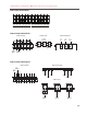
75C Cu Wire
6 AWG [10MM
2
] Max.
12 IN. LBS.
1.4 N-M
} TORQUE
WIRE
STRIP
CONTROL
POWER
BR1 BR2 DC+ DC- U/T1 V/T2 W/T3 R/L1 S/L2 T/L3
Optional
Communications
Module
PE B
PE A
75C Cu Wire
3 AWG [25MM
2
] Max.
16 IN. LBS.
1.8 N-M
} TORQUE
WIRE
STRIP
CONTROL
POWER
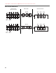
AUX IN
+ –
SHLD
SHLD
PE
75C Cu Wire
6 AWG [10MM
2
] Max.
BR1 BR2
12 IN. LBS.
1.4 N-M
} TORQUE
PE
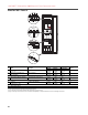
/
1
3
2
3
1
2
2
1
3