336 FORCE™ to PowerFlex® 700S Phase II Drive CONVERSION GUIDE
1336 FORCE™ To PowerFlex® 700S Phase II AC Drive Conversion Guide 2
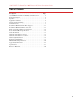
1336 FORCE™ To PowerFlex® 700S Phase II AC Drive Conversion Guide Table of Contents Description . . . . . . . . . . . . . . . . . . . . . . . . . . . . . . . . . . . . . . . . . Page 1336 FORCE™ AC Drive Availability Schedulerevision . . . . . . . . . 4 Product Description . . . . . . . . . . . . . . . . . . . . . . . . . . . . . . . . . . . . . . 4 Operation . . . . . . . . . . . . . . . . . . . . . . . . . . . . . . . . . . . . . . . . . . . . . . 5 Application Solutions. . . . . . . . . . . . . . . . .
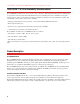
1336 FORCE™ To PowerFlex® 700S Phase II AC Drive Conversion Guide 1336 FORCE™ AC Drive Availability Schedulerevision The 1336 FORCE (1336T) was moved to an inactive stage on October 1, 2007 - Rockwell Automation, Inc. will no longer accept orders for new drive units. Rockwell Automation has been an industry leader in its commitment to long term customer support of drive products. This demonstrated commitment is unmatched in today’s global drives market.
1336 FORCE™ To PowerFlex® 700S Phase II AC Drive Conversion Guide Operation 1336 FORCE • FORCE Technology, a patented technique of Field-Oriented Control, to achieve the high performance speed and torque control of an AC motor. FORCE Technology is the first AC motor control technology that can truly achieve dynamic “DC-like” performance. • Speed and torque regulation capability without the need for an encoder.
1336 FORCE™ To PowerFlex® 700S Phase II AC Drive Conversion Guide Application Solutions 1336 FORCE The 1336 FORCE drive can be applied to specialized applications with cyclic or high inertia loads, impact loads that require fast response, or other demanding requirements. With available drive configurations that include Standalone, Common AC or Common DC Bus lineups, line regeneration, or dynamic braking or high performance systems – the 1336 FORCE drive handles many specialized applications with ease.
1336 FORCE™ To PowerFlex® 700S Phase II AC Drive Conversion Guide Start Up and Programming 1336 FORCE • A Human Interface Module (HIM) provides programming, auto-tuning features, diagnostics and other information in full, easy to understand text. The standard display is a 2 line by 16 character backlit LCD screen. A Graphic Programming Terminal (GPT) is also available and provides a full numeric keypad, advanced parameter programming operations, and parameter upload/ download capabilities.
1336 FORCE™ To PowerFlex® 700S Phase II AC Drive Conversion Guide DriveExplorer™ Software DriveExplorer software is an entry-level package providing basic functionality for programming and maintaining Rockwell Automation drives. DriveExplorer features Windows® Explorer-style navigation to make drive set-up easy and faster than using a Human Interface Module (HIM).
1336 FORCE™ To PowerFlex® 700S Phase II AC Drive Conversion Guide Communications 1336 FORCE • Direct connection to Remote I/O provides a seamless digital interface to a PLC Controller. • Direct connection to Data Highway Plus (DH+™) makes it possible to program and monitor the drive using DriveTools32™ programming software. • Direct connection to ControlNet™ provides powerful function block programming capabilities and 4 real-time trend buffers.
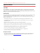
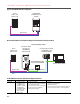
1336 FORCE™ To PowerFlex® 700S Phase II AC Drive Conversion Guide Typical 1336 FORCE Network Configuration PLC5 w/DH+ and Remote I/O 1336 FORCE with Multi-Comm Adapter Remote I/O DH+ Recommended Network Configuration Migration with PowerFlex 700S Phase II Drive ControlLogix Gateway Solution PLC5 w/DH+ and Remote I/O PowerFlex 700S with internal 20-COMM-R w/Remote I/O ControlLogix Controller with DHRIO Card and EN2T Module 20-XCOMM-DC-BASE w/internal 20-COMM-E Remote Work Station PORT MOD NET A NET
1336 FORCE™ To PowerFlex® 700S Phase II AC Drive Conversion Guide Option Type: Add EtherNet to PLC-5® Datalink Gateway Hardware Required: • Ethernet Side-card • 20-COMM-R (in drive) • 20-COMM-E (in box) • 20-XCOMM-DC-BASE • Ext. 24V DC supply • DIN rail to support 20XCOMM-DC-BASE & Ext. 24V DC supply • Ethernet cables • Datalink module w/ DH+ upgrade • 20-COMM-S (in box) • 20-COMM-R (in drive) • 20-XCOMM-DC-BASE • Ext. 24V DC supply • DIN rail to support 20XCOMM-DC-BASE & Ext.
1336 FORCE™ To PowerFlex® 700S Phase II AC Drive Conversion Guide PowerFlex 700S Phase II Drive Selection Position 1-3 20D 4 5-7 8 9 10 11 12 13 14 15 16 D 2P1 A 0 E Y N A N A N E b c d e f g h i j k l m a a c2 c3 Drive ND Rating ND Rating 400V, 50 Hz Input Code Type 20D PowerFlex 700S b Voltage Rating Code Voltage Ph. Prechg. 17 480V, 60 Hz Input Code Amps kW Code Amps Hp 2P1 2.1 0.75 2P1 2.1 1.0 3P5 3.5 1.5 3P4 3.4 2.0 5P0 5.0 2.
36 FORCE™ To PowerFlex® 700S Phase II AC Drive Conversion Guide c4 c5 j ND Rating ND Rating Comm Slot 600V, 60Hz Input ♣ 690V, 50 Hz Input ♣ Code Version Code Amps Hp Code Amps kW N None 1P7 1.7 1 052 52 45 C DPI ControlNet (Coax) 2P7 2.7 2 060 60 55 D DPI DeviceNet 3P9 3.9 3 082 82 75 E DPI EtherNet/IP 6P1 6.1 5 098 98 90 R DPI RIO 9P0 9 7.
1336 FORCE™ To PowerFlex® 700S Phase II AC Drive Conversion Guide Frame to AC Drive Rating Cross Reference 400V AC Input (using 700S kW ratings values) ND Cont. ND kW HD kW Output Amps 1336 Frame PF 700S Frame 0.75 0.55 2.1 B 1 1.5 1.1 3.5 B 1 2.2 1.5 5.0 B 1 4.0 3.0 8.7 B 1 5.5 4.0 11.5 B 1 7.5 5.5 15.4 B 1 11 7.5 22 B 1 15 11 30 B 2 18.5 15 37 B 2 22 18.
1336 FORCE™ To PowerFlex® 700S Phase II AC Drive Conversion Guide 600V AC Input (using 700S HP ratings values) ND HP 1 2 3 5 7.5 10 15 20 25 30 40 50 60 75 100 125 150 150 200 250 350 400 450 500 500 600 700 800 HD HP 0.75 1.5 2 3 5 7.5 10 15 20 25 30 40 50 60 75 100 125 150 150 200 250 350 350 400 500 500 650 700 ND Cont. Output Amps 1336 Frame PF 700S Frame 1.7 B 1 2.7 B 1 3.9 B 1 6.
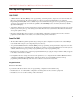
1336 FORCE™ To PowerFlex® 700S Phase II AC Drive Conversion Guide Power Terminal Block Specifications 1336 FORCE Table A Power Terminal Designations Terminal PE TE R (L1), S (L2), T (L3) +DC, -DC U (T1), V (T2), W (T3) Description Potential Earth Ground True Earth Ground AC Line Input Terminals DC Bus Terminals Motor Connection Frame B1 Power Terminal Block 200-240V, 0.75-5.5 kW (1-7.5 HP) 380-480/500-600V, 0.
1336 FORCE™ To PowerFlex® 700S Phase II AC Drive Conversion Guide Frame C Power Terminal Block 200-240V, 15-22 kW (20-30 HP) 380-480V, 30-45 kW (40-60 HP) 500-600V, 18.
1336 FORCE™ To PowerFlex® 700S Phase II AC Drive Conversion Guide Frame E Power Terminal Block 200-240V, 56-75 kW (75-100 HP) 380-480V, 112-187 kW (150-250 HP) 500-600V, 112-149 kW (150-200 HP) TE +DC –DC PE PE R-L1 BUS S-L2 INPUT T-L3 U-M1 To Motor V-M2 W-M3 OUTPUT To Motor Required 1 Input Fusing 1 Required Branch Circuit Disconnect AC Input Line Frame F Power Terminal Block 380-480V, 187-336 kW (250-450 HP) R-L1 S-L2 T-L3 Input Fusing (Supplied) PE U-M1 V-M2 W-M3 To Motor 1 Requ
1336 FORCE™ To PowerFlex® 700S Phase II AC Drive Conversion Guide Frame G Power Terminal Block 380-480V, 224-448 kW (300-600 HP) 500-600V, 187-485 kW (250-650 HP) Brake terminals are located on the DC choke behind the "U" terminal. Access the DC Choke from the right side of the chassis. S (L2) T (L3) R (L1) Connect the +DC Brake to the +Bus to the drive. Required Input Fusing U (M1) Required Branch Circuit Disconnect V (M2) W (M3) Connect the -DC Brake to the -Bus to the drive.
1336 FORCE™ To PowerFlex® 700S Phase II AC Drive Conversion Guide Power Terminal Block Locations TB9 TB3 TB4 TB6 TB3 TB10 TB10 Control Interface Option TB1 Control Interface Option TB3 TB11 TB1 Frames B, C TB1 Location TB4 TB11 TE TB6 TB1 Location TB1 Brake Terminals TB1 Frames D, E R, S, T Frame F +, - TB3 TB3 TB10, 11 TE TB1 Location U, V, W & Brake Terminals TB10, 11 TE TB1 Location PE Ground Frame G Table B Terminal Block Designations Terminal Block TB1 TB2 TB3 TB4 TB6 TB9 TE 20
1336 FORCE™ To PowerFlex® 700S Phase II AC Drive Conversion Guide Table C Power Terminal Block (TB1) Specifications Max./Min. Wire Size (4) mm2 (AWG) 8.4/0.8 (8/18) 13.3/0.5 (6/20) 26.7/0.8 (3/18) 120.0/2.1 (4/0 /14) 67.4/2.1 (00/14) (5) 253.0/2.1 (500 MCM/14) 303.6/2.1 (600 MCM/14) 303.6/2.1 (600 MCM/14) Drive Frame Size B1 B2 C D (1), (2) E (1), (3) F (1) G (1) (1) (2) (3) (4) (5) Maximum Torque N-m (lb.-in.) 1.81 (16) 1.70 (15) 5.65 (50) 6.00 (52) 6.00 (52) 10.00 (87) 23.00 (200) 23.
1336 FORCE™ To PowerFlex® 700S Phase II AC Drive Conversion Guide Frame 5 Power Terminal Blocks 75 HP Normal Duty - 480V AC Input BR1/ BR2 DC+ DC+ DC– U/T1 V/T2 W/T3 PS– PE PE R/L1 S/L2 T/L3 100 HP Normal Duty - 480V AC Input PS+ BR2 DC+ BR1/ DC+ DC– U/T1 V/T2 R/L1 W/T3 PE S/L2 T/L3 PE PS– 75 HP Normal Duty - 650V DC Input BR1*/ BR2* DC+ DC+ DC– PS– U/T1 V/T2 W/T3 PS+ 0 240 VAC VAC PE PE 120 VAC PS+ 100 HP Normal Duty - 650V DC Input Precharge Resistor Fuse – FWP-15A14F (Common Bu
1336 FORCE™ To PowerFlex® 700S Phase II AC Drive Conversion Guide Frame 9 Power Terminal Blocks L1 L2 L3 L1 L2 L3 AC Line Input Power U/T1 V/T2 W/T3 U/T1 V/T2 W/T3 To Motor Leads Frame 10 Power Terminal Blocks DC Bus Terminals To Motor Leads Input Power Terminals V/T2 U/T1 L1 L2 L3 W/T3 DC- DC+ Frame 11 Power Terminal Blocks DC Bus Terminals Input Power Terminals DC+ DC1L1 1L3 2L1 1L2 2L3 2L2 To Motor Leads U/T1 V/T2 W/T3 23
1336 FORCE™ To PowerFlex® 700S Phase II AC Drive Conversion Guide Frame 12 Power Terminal Blocks DC Bus Terminals (One each enclosure) To Motor Leads 1V/T2 1U/T1 Input Power Terminals 1L1 1L2 1L3 1W/T3 DC- DC+ 2V/T2 2U/T1 DC- DC+ 24 2L1 2L2 2L3 1W/T3
1336 FORCE™ To PowerFlex® 700S Phase II AC Drive Conversion Guide Power Terminal Block Locations Frames 1 - 4 Power Terminal Block Locations and Specifications Frame 1 Frames 3 & 4 Frame 2 3 Optional Communications Module ! DANGER Optional Communications Module Use 75C Wire Only #10-#14 AWG 1 Torque to 7 in-lbs PE B PE A BR1 U/T1 PE R/L1 S/L2 T/L3 3 WIRE STRIP BR1 BR2 75C Cu Wire 6 AWG [10MM2] Max. 12 IN. LBS. 1.
1336 FORCE™ To PowerFlex® 700S Phase II AC Drive Conversion Guide PowerFlex 700S - Frames 5 & 6 Frame 6 Frame 5 2 Optional Communications Module 2 Optional Communications Module 4 4 3 300 VDC EXT PWR SPLY TERM (PS+, PS-) POWER TERMINAL RATINGS WIRE RANGE: 14-1/0 AWG (2.5-35 MM2) TORQUE: 32 IN-LB (3.6 N-M) STRIP LENGTH: 0.67 IN (17 MM) USE 75 C CU WIRE ONLY WIRE RANGE: 22-10 AWG (0.5-4 TORQUE: 5.3 IN-LB (0.6 N-M) STRIP LENGTH: 0.
1336 FORCE™ To PowerFlex® 700S Phase II AC Drive Conversion Guide PowerFlex 700S - Frame 9 3 2 D C – D C +/ R + – R 1 1 2 4 Wire Size Range(1) Maximum Minimum 95.0 mm2 185.0 mm2 350 MCM 4/0 AWG Torque Maximum 40 N-m (340 lb.-in.) Terminal Recommended Bolt Size(2) 40 N-m — (340 lb.-in.) Terminating point for wiring shields 95.0 mm2 4/0 AWG 5.0 mm2 10 AWG 22 N-m (187 lb.-in.) 22 N-m (187 lb.-in.
1336 FORCE™ To PowerFlex® 700S Phase II AC Drive Conversion Guide PowerFlex 700S - Frame 10 V/T2 Cat No. FIELD INSTALLED OPTIONS: 1234567890-* 4 1234567890-* DCDC+ DANGER DC BUS CONDUCTORS AND CAPACITORS OPERATE AT HIGH VOLTAGE. REMOVE POWER AND WAIT 5 MINUTES BEFORE SERVICING U/T1 W/T3 2 L1 1 L2 L3 5 3 No. 1 2 Name Input Power Terminal Block L1, L2, L3(3) Output Power Terminal Block ((3) U/T1, V/T2, W/T3 Description Input power Motor connections Wire Size Range (1)(2) Maximum Minimum 2.
1336 FORCE™ To PowerFlex® 700S Phase II AC Drive Conversion Guide PowerFlex 700S - Frame 11 DC+ 4 DC- 2 U/T1 1L1 V/T2 1L3 1L2 No. 1 W/T3 2L1 1 3 2L3 2L2 Wire Size Range (1) (2) Maximum Minimum 300 mm2 2.1 mm2 (600 MCM) (14 AWG) 300 mm2 2.1 mm2 (600 MCM) (14 AWG) Torque Recommended 40 N-m (354 lb.-in.) 40 N-m (354 lb.-in.) Terminal Bolt Size Terminating point for wiring shields 300 mm2 (600 MCM) 2.1 mm2 (14 AWG) 40 N-m (354 lb.-in.) M10 DC input 300 mm2 (600 MCM) 2.
1336 FORCE™ To PowerFlex® 700S Phase II AC Drive Conversion Guide Power Terminal Specifications, Frame 12 4 4 DC- DC+ DC- DC+ Cat No. FIELD INSTALLED OPTIONS: 2V/T2 1234567890-* 1V/T2 DANGER DANGER 2 OPERATE AT HIGH VOLTAGE. REMOVE POWER AND WAIT 5 MINUTES BEFORE SERVICING AND WAIT 5 MINUTES BEFORE SERVICING 1U/T1 1 2 DC BUS CONDUCTORS AND CAPACITORS DC BUS CONDUCTORS AND CAPACITORS OPERATE AT HIGH VOLTAGE. REMOVE POWER 1W/T3 1L1 1L2 1L3 2U/T1 2W/T3 2L1 2L2 2L3 1 5 5 3 No.
1336 FORCE™ To PowerFlex® 700S Phase II AC Drive Conversion Guide Control Terminals PowerFlex 700S Table D TB1 Terminals 1 2 3 4 5 6 7 Terminal 1 2 3 4 5 6 8 9 10 11 12 13 14 15 16 17 18 19 20 21 22 23 24 7 8 9 10 11 12 13 14 15 16 17 18 19 20 21 22 23 24 (1) Signal Analog Input 1 Comm. Analog Input 1 (+/-) Shield Analog Input 2 Comm. Analog Input 2 (+/-) Analog Input 3 [NTC-] Comm.
1336 FORCE™ To PowerFlex® 700S Phase II AC Drive Conversion Guide Table E TB2 Terminals 1 2 Terminal 1 2 3 3 4 5 6 7 8 9 10 11 12 13 14 15 16 4 5 6 7 8 9 10 11 12 13 14 15 16 Signal 24V DC Common (-) 24V DC Source (+) Digital Output 1 Factory Default Description NA Drive supplied 24V DC logic input power NA Rating: 300 mA maximum load 24V DC Open Collector (sinking logic) Rating: Internal Source = 150 mA max.
1336 FORCE™ To PowerFlex® 700S Phase II AC Drive Conversion Guide A good example of recommended cable is Belden® 295xx (xx determines gauge). This cable has four (4) XLPE insulated conductors with a 100% coverage foil and an 85% coverage copper braided shield (with drain wire) surrounded by a PVC jacket. Other types of shielded cable are available, but the selection of these types may limit the allowable cable length.
1336 FORCE™ To PowerFlex® 700S Phase II AC Drive Conversion Guide Cable Recommendations - Control Table G Recommended Control Wire Type Digital I/O Standard Analog I/O Remote Pot Encoder/Pulse I/O Less 30.5 m (100 ft.) Encoder/Pulse I/O 30.5 m (100 ft.) to 152.4 m (500 ft.) Encoder/Pulse I/O 152.4 m (500 ft.) to 259.1 m (850 ft.
1336 FORCE™ To PowerFlex® 700S Phase II AC Drive Conversion Guide Cable Length Restrictions Important: In the following tables, A “●” in any of the latter columns will indicate that this drive rating can be used with an Allen-Bradley Terminator (1204-TFA1/1204-TFB2) and/or Reflected Wave Reduction Device with Common Mode Choke (1204-RWC-17) or without choke (1204-RWR2). For the Terminator, the maximum cable length is 182.9 meters (600 feet) for 400/480/600V drives (not 690V).
5 55 75 6 90 110 132 9 132 160 10 200 250 11 315 355 400 12 (1) 450 500 560 630 (2) 13 710 (2) 800 (2) (1) (2) (3) (4) (5) kHz 1000V 1200V 2/4 12.2 106.9 (40) (350) 2/4 12.2 106.9 (40) (350) 2/4 18.3 91.4 (60) (300) 2/4 18.3 91.4 (60) (300) 2/4 24.4 91.4 (80) (300) 2/4 24.4 91.4 (80) (300) 2 24.4 91.4 (80) (300) 2 24.4 91.4 (80) (300) 2 24.4 76.2 (80) (250) 2 24.4 76.2 (80) (250) 2 18.3 68.6 (60) (225) 2 18.3 68.6 (60) (225) 2 18.3 68.6 (60) (225) 2 18.3 68.6 (60) (225) 2 12.2 68.
1336 FORCE™ To PowerFlex® 700S Phase II AC Drive Conversion Guide 3 4 5 6 9 10 11 12 (1) 13 (1) (2) (3) (4) (5) 1488V 106.9 (350) 106.9 (350) 106.9 (350) 106.9 (350) 106.9 (350) 91.4 (300) 91.4 (300) 91.4 (300) 91.4 (300) 91.4 (300) 91.4 (300) 91.4 (300) 91.4 (300) 61.0 (200) 61.0 (200) 61.0 (200) 61.0 (200) 61.0 (200) 61.0 (200) 61.0 (200) 61.0 (200) 61.0 (200) 61.0 (200) 61.0 (200) 1600V 152.4 (500) 152.4 (500) 152.4 (500) 152.4 (500) 152.4 (500) 152.4 (500) 152.4 (500) 137.2 (450) 137.
1336 FORCE™ To PowerFlex® 700S Phase II AC Drive Conversion Guide Table J PowerFlex 700S, 600V Shielded/Unshielded Cable - Meters (Feet) (1) (2) (3) (4) (5) 1850V 121.9 (400) 152.4 (500) 152.4 (500) 152.4 (500) 152.4 (500) 152.4 (500) 152.4 (500) 152.4 (500) 152.4 (500) 152.4 (500) 152.4 (500) 152.4 (500) 152.4 (500) 152.4 (500) 152.4 (500) 152.4 (500) 152.4 (500) 152.4 (500) 152.4 (500) 152.4 (500) 152.4 (500) 152.4 (500) 152.4 (500) 152.4 (500) 152.4 (500) 152.4 (500) 152.4 (500) 152.4 (500) 152.
1336 FORCE™ To PowerFlex® 700S Phase II AC Drive Conversion Guide (1) (2) (3) (4) (5) 2000V 68.6 (225) 68.6 (225) 68.6 (225) 68.6 (225) 68.6 (225) 68.6 (225) 68.6 (225) 68.6 (225) 68.6 (225) 1850V 76.2 (250) 76.2 (250) 61.0 (200) 61.0 (200) 61.0 (200) 61.0 (200) 61.0 (200) 48.8 (160) 48.8 (160) 2000V 121.9 (400) 121.9 (400) 91.4 (300) 91.4 (300) 91.4 (300) 91.4 (300) 91.4 (300) 91.4 (300) 91.4 (300) Resistor 1850V 243.8 (800) 243.8 (800) 243.8 (800) 243.8 (800) 243.8 (800) 243.8 (800) 243.8 (800) 243.
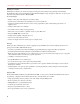
1336 FORCE™ To PowerFlex® 700S Phase II AC Drive Conversion Guide Minimum Mounting Clearances 1336 FORCE All Frames Important: F & G Frame drives require a minimum of 152.4 mm (6.0 in.) between the drive back and mounting wall, if drives are mounted with sides touching another device or wall. A minimum of 76.2 mm (3.0 in.) is required on the sides if the back of the drive is mounted against a wall or other device. 101.6mm (4.0 in.) 152.4mm (6.0 in.) 152.4mm (6.0 in.) PowerFlex 700S Frames 1-6 101.
1336 FORCE™ To PowerFlex® 700S Phase II AC Drive Conversion Guide Frame 9 400.0 mm 400.0 mm (15.75 in.)mm 400.0 (15.75 400.0 mm in.) (15.75 in.) (15.75 in.) 50.0 mm50.0 mm (1.97 in.) (1.97 in.) 50.0 mm 50.0 mm (1.97 in.) 80.0 mm 80.0 mm (3.2 in.) (3.2 in.) (1.97 in.) 350.0 mm (13.8 in.) 350.0 mm (13.8 in.) 350.0 mm (13.8 in.) 350.0 mm (13.8 in.) Frames 10 - 13 (Frame 10 shown) Powerful Performance, Flexible Control. 1m (39.4) 152.4 (6.00) 152.4 (6.
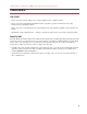
Frame B1, B2 C 1 2 3 B Dimensions(1) mm (in.) A (700S Slim) AA (700S Expanded) 276.4 (10.88) na 301.8 (11.88 na 135.0 (5.31) 166.9 (6.57) 222.0 (8.74) 253.9 (9.99) 222.0 (8.74) 253.9 (9.99) B 476.3 (18.75) 701.0 (27.60) 336.0 (13.23) 342.5 (13.48) 517.5 (20.37) Mounting Holes (4) E C (Max.) 225.0 (8.86) 225.0 (8.86) 200.0 (7.87) 200.0 (7.87) 200.0 (7.87) C Max. D 212.6 (8.37) 238.0 (9.37) 105.0 (4.13) 192.0 (7.56) 192.0 (7.56) 42 Weight (2) kg (lbs.) Drive na na 7.03 (15.5) 12.52 (27.6) 18.55 (40.
Frame C 4 B Dimensions(1) mm (in.) A (700S Slim) AA (700S Expanded) 301.8 (11.88 na 220.0 (8.66) 251.9 (9.92) B 701.0 (27.60) 758.8 (29.87) Mounting Holes (4) E C (Max.) 225.0 (8.86) 201.7 (7.94) C Max. D 238.0 (9.37) 192.0 (7.56) 312 (12.28) 8.0 (0.31) 3 Places S 7.0 (0.27) 2 Places AA A D E 685.8 (27.00) 738.2 (29.06) Lifting Holes 4 Places Refer to drive User Manuals for location and size of motor lead knockouts.
Frame D 4 Dimensions(1) mm (in.) A (700S Slim) AA (700S Expanded) 381.5 (15.02) na 220.0 (8.66) 251.9 (9.92) E B C Max. B 1240.0 (48.82) 758.8 (29.87) 1336 FORCE C (Max.) 270.8 (10.66) 201.7 (7.94) D 325.9 (12.83) 192.0 (7.56) 312 (12.28) 44 8.0 (0.31) 3 Places S 7.0 (0.27) 2 Places AA A D E 1216.2 (47.88) 738.2 (29.06) Lifting Holes 4 Places Refer to drive User Manuals for location and size of motor lead knockouts.
Frame D 5 Dimensions(1) mm (in.) A (700S Slim) AA (700S Expanded) 381.5 (15.02) na 308.0 (12.16) 339.9 (13.38) Mounting Holes (4) E B C Max. B 1240.0 (48.82) 644.5 (25.37) (2) 1336 FORCE C (Max.) 270.8 (10.66) 275.4 (10.84) 12.5 (0.49) E 312 (12.28) D 325.9 (12.83) 225.0 (8.86) B 37.6 (1.48) A S 6.5 (0.26) HOT surfaces can cause severe burns CAUTION D 259.1 (10.20) AA E 1216.2 (47.88) 625.0 (24.61) Refer to drive User Manuals for location and size of motor lead knockouts.
Frame D 6 Dimensions(1) mm (in.) A (700S Slim) AA (700S Expanded) 381.5 (15.02) na 403.9 (15.90) 435.8 (17.16) Mounting Holes (4) E B B 1240.0 (48.82) 850.0 (33.46) 1336 FORCE C Max. C (Max.) 270.8 (10.66) 275.5 (10.85) E D 325.9 (12.83) 300.0 (11.81) 126.3 (4.97) B 13.5 (0.53) 312 (12.28) 49.6 (1.95) 46 8.5 (0.33) E 1216.2 (47.88) 825.0 (32.48) Refer to drive User Manuals for location and size of motor lead knockouts.
Dimensions(1) mm (in.) Frame A (700S Slim) AA (700S Expanded) E (enclosed) 511.0 (20.1) na 6 403.9 (15.9) 435.8 (17.2) Mounting Holes (4) E B 1336 FORCE B 1498.6 (59.0) 850.0 (33.5) C Max. C (Max.) 424.4 (16.7) 275.5 (10.9) E 13.5 (0.53) D 477.5 (18.8) 300.0 (11.8) 126.3 (4.97) B 312 (12.28) 49.6 (1.95) Refer to drive User Manuals for location and size of motor lead knockouts.
C Max. Weight (2) kg (lbs.) B E Refer to drive User Manuals for location and size of motor lead knockouts. PowerFlex 700S weights include HIM, DriveLogix controller with ControlNet daughtercard, Hi-Resolution Encoder Option, and 20-COMM-C ControlNet adapter. 48 (1) (2) E B 1336 FORCE D A S Wire Way Lifting Hole 21.0 (0.83) Nameplate C Drive & Packaging (400/480V AC - 300A 700S only) na 213 (470) PowerFlex 700S B C (Max.) D E Drive Drive & Packaging Drive (400/480V AC - 300A 700S only) 1498.
Frame F 10 Dimensions(1) mm (in.) A B 762.0 (30.0) 2286.0 (90.0) 635.0 (25.0) 2286.0 (90.0) B BB na 2349.5 (92.5) Refer to drive User Manuals for location and size of motor lead knockouts. Drive 1336T 700S (1) ) A 1336 FORCE C C 635.0 (25.0) 635.0 (25.0) CC CC 672.9 (26.5) na Weight kg (lbs.) Drive (400V Class) na 454 (1100) Drive (600V Class) na 449 (990) Powerful Performance, Flexible Control.
Frame G 10 Dimensions(1) mm (in.) A B 762.0 (30.0) 2324.1 (91.5) 635.0 (25.0) 2286.0 (90.0) B BB BB 2387.6 (94.0) 2349.5 (92.5) 1336 FORCE 50 Refer to drive User Manuals for location and size of motor lead knockouts. Drive 1336T 700S (1) ) A C 635.0 (25.0) 635.0 (25.0) Removable Lifting Angle C Weight kg (lbs.) Drive (400V Class) na 454 (1100) Drive (600V Class) 454 (1000) 449 (990) Powerful Performance, Flexible Control.
Frame G 11 Dimensions(1) mm (in.) A B 762.0 (30.0) 2324.1 (91.5) 889.0 (35.0) 2286.0 (90.0) B BB 1336 FORCE C C 635.0 (25.0) 635.0 (25.0) Removable Lifting Angle BB 2387.6 (94.0) 2349.5 (92.5) Refer to drive User Manuals for location and size of motor lead knockouts. Drive 1336T 700S (1) ) A Weight kg (lbs.) Drive (400V Class) na 696 (1535) Drive (600V Class) na 640 (1411) A Drive & Packaging (400V) 454(1000.
) (1) B BB Dimensions(1) mm (in.) A AA AAA 1270 (50.0) 762.0 (30.0) 508.0 (20.0) 1270 (50.0) 635 (25.0) na AAA Removable Lifting Angle C B BB C 2324.1 (91.50) 2387.6 (94.00) 635 (25.0) 2286 (90.0) 2349.5 (92.5) 635 (25.0) Refer to drive User Manuals for location and size of motor lead knockouts. Drive Frame 1336T H 700S 12 AA A 1336 FORCE Powerful Performance, Flexible Control. AA B BB Removeable Lifting Angle C Weight kg (lbs.
Category Protection Calculated value, 105% of motor rated to 200% of drive rated 105% of 3 sec. rating (158%-210%) 143% of 3 sec rating (215%-287%) Up to 6000 volts peak per IEEE C62.41-1991 Showering arc transients up to 1500V peak 15 milliseconds at full load 0.25 sec., drive not running Phase-to-ground on drive output Phase-to-phase on drive output up to 6000 volts peak per IEEE C62.41-1991 Showering arc transients up to 1500V peak 15 milliseconds at full load 0.
C-Tick ATEX TÜV CE c-UL-us Category Specification Agency Certification 1336 FORCE Drive — PowerFlex 700S Phase II Drive Frames 1-6 (690V Drive frames 5 & 6 only) PowerFlex 700S Phase II Drive Frames 9 & up — The drive is designed to meet applicable requirements of the The drive is designed to meet applicable requirements of the following codes/standards: following codes/standards: IEC 61800-2 Adjustable speed electrical power drive systems - IEC 61800-2 Adjustable speed electrical power drive system
5 to 95% non-condensing 10G peak for 11 ms duration (± 1.0 ms) 0.152 mm (0.006 in.) displacement, 1G peak, 5.5 Hz Frame 5 to 95% non-condensing 15G peak for 11ms duration (±1.0 ms) 0.152 mm (0.006 in.) displacement, 1G peak — — Sound Atmosphere Electrical DC Input Voltage Tolerance Displacement Power Factor: Efficiency: Max. Short Circuit Current Rating: Maximum Drive to Motor Power Ratio AC Input Voltage Tolerance: Frequency Tolerance: Input Phases: 2 mm (0.0787 in.
Category Control Current Limit Capability: Electronic Motor Overload Protection S-Curve Time Intermittent Overload: Accel/Decel Stop Modes: Selectable Motor Control: Torque Regulation Speed Control Output Voltage Range: Output Frequency Range: Specification Method Induction Motor: Brushless Motor: Carrier Frequency Field Oriented Control with and without a feedback device.
Category Feedback 12V DC, 500 mA 5V or 12V, 10mA Min. Inputs 1336 FORCE Drive Incremental, dual channel, isolated with differential transmitter, Quadrature: 90° ±27° @ 25°C, Duty Cycle: 50% + 10%. — Resolver Option: Excitation Frequency: Excitation Voltage: Operating Freq. Range: Resolver Fdbk Voltage: Max. Cable Length: Customer-I/O Plug (P1) - Hi Res: — Maximum Input Frequency: 102.5 kHz — Stegmann Option: Encoder Volt. Supply: Hi-Resolution Fdbk.: Max.
Category DriveLogix Compact I/O Connection: Cable: Specification User Available MemoryBase: Battery: Serial Cable: 1336 FORCE Drive — 1769-BA 0.59g lithium 1761-CBLPM02 to 1761-NET-AIC 1761-CBLPA00 to 1761-NET-AIC 1756-CP3 directly to controller 1747-CP3 directly to controller category 3 (2) Up to (16) modules 20D-DL2-CL3, 20D-DL2-CR3 PowerFlex 700S Phase II Drive Frames 1-6 (690V Drive frames 5 & 6 only) 1.
1336 FORCE™ To PowerFlex® 700S Phase II AC Drive Conversion Guide 380-400 Nominal Line Voltage 200 208 240 380 400 480 600 500-600 (Frames 1-4 Only) 500-690 600 (Frames 5 & 6 690 Only) Drive Full Power Range = Drive Operating Range = Nominal Motor Voltage 200† 208 230 380† 400 460 575† Drive Full Power Range 200-264 208-264 230-264 380-528 400-528 460-528 575-660 Drive Operating Range 180-264 575† 690 575-660 690-759 475-759 475-759 342-528 Derated Power Range No Drive Output Full Power Range
Reference Materials The following publications provide general drive information. Title Wiring and Grounding for PWM AC Drives Safety Guidelines for the Application, Installation and Maintenance of Solid State Control A Global Reference Guide for Reading Schematic Diagrams Guarding Against Electrostatic Damage Publication DRIVES-IN001... SGI-1.1... 100-2.10... 8000-4.5.2... Available… www.rockwellautomation.