
Manual

Appendix A
A–27
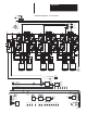
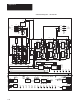
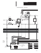
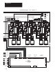
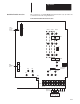
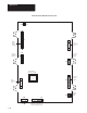
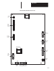
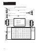
Gate Driver Board Connections The connections on 1336 FORCE Gate Driver Boards vary by frame size
as indicated in the following illustrations
:
1
J1
1
10
+ BUS
E25
Main
Control
Board
Interface
TB1
E26 E1
E6
E5
PE
GND
PE
GND
DC
+
DC
–
R
(L1)
S
(L2)
T
(L3)
U
(T1)
V
(T2)
W
(T3)
E20 E19 E21
E29
E22
50
E8
E27
E13 E15 E11
LEM2
LEM1
E16 E12 E14
E10 E9 E17
J4
E18
F1
– BUS Motor
To Motor
AC Input Line
Required
Input Fusing
Required Branch
Circuit Disconnect
FAN
Precharge
Resistor
Bus
Switcher
Fuse
Frame Size B Gate Driver Board Connections