
Manual

Chapter 5
Programming Parameters
5–51
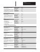
Velocity Regulator Testpoint Select
[Vel Reg TP Sel]
Velocity Error
[Velocity Error]
Parameter Number 138
Parameter Type Source
Display Units +/– x.x rpm
Drive Units 4096 = Base Motor Speed
Factory Default +0.0 rpm
Minimum Value – 8 x Base Speed rpm
Maximum Value +8 x Base Speed rpm
Parameter Number 137
Parameter Type Sink
Display Units x
Drive Units None
Factory Default 0
Minimum Value 0
Maximum Value 15
This parameter selects which internal loca-
tion of the velocity reference will become
the testpoint value shown in Vel Reg TP
Low P135 & Vel Reg TP Hi P136. The fol-
lowing are the internal locations based
upon the select value:
Select Value Velocity Reference Access Point
0 Zero
1 Droop Speed Offset (32bit)
2 Drooped Velocity Reference (32 bit)
3 Kf Term (Low), Kf Err (High)
4 Kf Error Filter Output 1 (Low), Kf Error Filter Output 2 (High)
5 Kp Term (32 bit)
6 Or – 1st 16 bit (Low), 2nd 16 bit (High)
7 Or – 3rd 16 bit (Low), 4th 16 bit (High)
8 Of – 1st 16 bit (Low), 2nd 16 bit (High)
9 Of – 3rd 16 bit (Low), 4th 16 bit (High)
10 Oe – 1st 16 bit (Low), 2nd 16 bit (High)
11 Oe – 3rd 16 bit (Low), Not Used (High)
12 Oec1 – 1st 16 bit (Low), 2nd 16 bit (High)
13 Oec1 – 3rd 16 bit (Low), 4th 16 bit (High)
14 Ki Term (32 bit)
15 Logic Control Word (LOW) Integrator Enable Flag (HIGH)
This parameter contains a value that is the
difference between the whole number por-
tion of the velocity regulator’s reference
input and the velocity feedback.
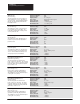
KI – Velocity Loop
[Ki – Velocity Loop]
Parameter Number 139
Parameter Type Sink
Display Units x.x
Drive Units Display units x 8
Factory Default 32.0
Minimum Value 0.0
Maximum Value 4096.0
KP – Velocity Loop
[Kp – Velocity Loop]
Parameter Number 140
Parameter Type Sink
Display Units x.x
Drive Units Display units x 8
Factory Default 8.0
Minimum Value 0.0
Maximum Value 200.0
This parameter controls the integral error
gain of the velocity regulator. Gain has a
resolution of 1/8, therefore a Ki gain of 1.0
is converted to internal drive units as a val-
ue of 8.
This parameter controls the proportional
error gain of the velocity regulator. Gain
has a resolution of 1/8, therefore a gain of
1.0 is converted to internal drive units as a
value of 8.
KF – Velocity Loop
[Kf – Velocity Loop]
Parameter Number 141
Parameter Type Sink
Display Units x.xx
Drive Units Display units x 65535
Factory Default 1.00
Minimum Value 0.50
Maximum Value 1.00
This parameter controls the feed forward
gain of the velocity regulator. Setting the
Kf gain to less than one reduces velocity
feedback overshoot in response to a step
change in velocity reference.
KF Error Filter Bandwidth
[Error Filter BW]
Parameter Number 142
Parameter Type Sink
Display Units x Radian/Seconds
Drive Units None
Factory Default 500 Radian/Seconds
Minimum Value 0
Maximum Value 1500 Radian/Seconds
This parameter sets the bandwidths of two
cascaded low pass filters in the Kf error
path of the Velocity PI Regulator. Band-
width is entered in units of radians per
second.