
Manual

Chapter 5
Programming Parameters
5–46
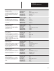
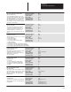
Fault Testpoint Data
[Fault TP]
Parameter Number 98
Parameter Type Source
Display Units x
Drive Units None
Factory Default 0
Minimum Value 0
Maximum Value 65535
This parameter contains the fault control
testpoint data that has been selected by
the Fault TP Sel parameter(P99). See the
description for the Fault TP Sel parameter
99 for a list of possible testpoints.
Select Value Velocity Reference Access Point
0 Zero
1 Adapter Processor Faulted
2 Actual Velocity when Overspeed occurred
3 Motor Overload Calibration Constant (K)
4 Heatsink NTC Analog Input Voltage
5 Heatsink NTC Foldback Current Limit
6 Negative Analog Supply and/or input voltage
7 Positive Analog Supply and/or input Voltage
8 Zero
9 Motor Overload Integrator(I
2
T) level
10 Dynamic Brake Resistor Temperature, Degrees C.
11 Parameter Limit Status, Word 1
12 Parameter Limit Status, Word 2
13 Velocity Reference Math Overflow Status
14 Velocity Feedback Math Overflow Status
15 Velocity Regulator Math Overflow Status
16 Torque Reference Math Overflow Status
17 Process Trim Math Overflow Status
VELOCITY Feedback Error Conditions:
18 Acceleration Error
19 Illegal State Edge Samples
20 Illegal State Level
21 Encoder Loss Edge Samples
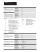
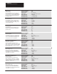
Fault Testpoint Select
[Fault TP Sel]
Parameter Number 99
Parameter Type Sink
Display Units x
Drive Units None
Factory Default 0
Minimum Value 0
Maximum Value 32
Enums:
This parameter selects which internal loca-
tion in the fault control software will be-
come the testpoint value. The value based
upon the selection will be stored in the
Fault TP parameter 98. The internal loca-
tions of the logic control software that are
accessible based on the selected value are
listed below:
Select Value Velocity Ref Access Point
22 Encoder Loss Level
23 Iq Reference in per unit Inverter Units
24 Motor Overload Integrator Output Level (IT)
25 Motor Temperature, Degrees C.
26 Drive to Drive fault status
27 Base Drive EE fault status
28 Base Drive EE drive type address
29 Base Drive EE drive type data
30 Heatsink Warn Temp, deg C.
31 Heatsink Trip Temp, deg. C.
32 Zero
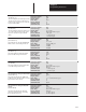
Velocity Reference 1 LOW (Fraction)
[Vel Ref 1 Low]
Parameter Number 100
Parameter Type Sink
Display Units x
Drive Units None
Factory Default 0
Minimum Value 0
Maximum Value 65535
This word supplies the fractional part of the
external velocity reference 1 when
external velocity control has been selected
in Logic Command (P52).
Velocity Reference 1 HI (Whole 32 bit)
[Velocity Ref 1 Hi]
Parameter Number 101
Parameter Type Sink
Display Units +/– x.x rpm
Drive Units 4096 = Base Motor Speed
Factory Default + 0.0 rpm
Minimum Value – 8 x Base Speed
Maximum Value +8 x Base Speed
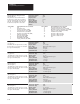
Velocity Scale Factor 1
[Vel Scale Fctr 1]
Parameter Number 102
Parameter Type Sink
Display Units +/– x.xxxx
Drive Units 8192 = 1.0000 gain
Factory Default + 1.0000
Minimum Value – 4.0000
Maximum Value + 4.0000
This word supplies the whole number part
of external velocity reference 1 when the
external velocity control has been selected
in Logic Command (P52).
This parameter sets the gain multiplier that
will be used to scale velocity reference 1.