
Manual

Chapter 5
Programming Parameters
5–38
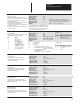
Local Input Status
[Local In Status]
Parameter Number 54
Parameter Type Source
Display Units Bits
Drive Units Bits
Factory Default 0000 0000 0000 0000
Minimum Value 0000 0000 0000 0000
Maximum Value 1111 1111 1111 1111
Enums:
This parameter indicates boolean input sta-
tus conditions for the Velocity Processor.
When a bit is set to 1, the corresponding
input signal is true.
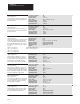
Local Output Status
[Local Out Status]
Parameter Number 55
Parameter Type Source
Display Units Bits
Drive Units Bits
Factory Default 0000 0000 0000 0000
Minimum Value 0000 0000 0000 0000
Maximum Value 1111 1111 1111 1111
Enums:
This parameter indicates boolean output
status conditions for the Velocity Proces-
sor. When a bit is set to 1, the correspond-
ing input signal is true.
Value Description
0 Brake Request
1 Drive Enable
2 Motor Overtemp Thermoguard
3 Discrete Stop
Value Description
4 External Fault
5 RMS Fault
6 0 = Parall Inv
7 Single Lang
Value Description
8 Test Diag
9 Inverter Status
10 Contactor Verify
11 Not Used
Value Description
12 Not Used
13 Not Used
14 Not Used
15 Not Used
Value Description
0 Brake Enable
1 Turn On Delay Select
2 Not Used
3 Not Used
Value Description
4 Not Used
5 Not Used
6 Not Used
7 Not Used
Value Description
8 Not Used
9 VP Enable
10 Pilot Relay
11 Not Used
Value Description
12 VP Green LED
13 VP Red LED
14 Not Used
15 Not Used
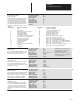
Logic Status Low
[Logic Status Low]
Parameter Number 56
Parameter Type Source
Display Units Bits
Drive Units Bits
Factory Default 0000 0000 0000 0000
Minimum Value 0000 0000 0000 0000
Maximum Value 1111 1111 1111 1111
This parameter is the Low part of a double
word that indicates boolean logic condi-
tions within the Drive. When a bit is set to
1, the corresponding condition in the Drive
is true.
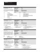
Logic Status Hi
[Logic Status Hi]
Parameter Number 57
Parameter Type Source
Display Units Bits
Drive Units None
Factory Default 0000 0000 0000 0000
Minimum Value 0000 0000 0000 0000
Maximum Value 1111 1111 11111 1111
Enums:
This parameter is the Hi part of a double
word that indicates boolean logic condi-
tions within the Drive. When a bit is set to
1, the corresponding condition in the Drive
is true.
Value Description
0 Ready to Run
1 Drive Running
2 Cmd Direction (1=FWD, 0=Rev)
3 Rotation Direction
(1=FWD, 0=Rev)
Value Description
4 Accelerating (1=Accel)
5 Decelerating (1=Decel)
6 Warning
7 Faulted
Value Description
8 At Set Speed
9 Local A
10 Local B
11 Local C
Value Description
12 At Zero Speed
13 Reference A
14 Reference B
15 Reference C
Value Description
0 Flux Ready
1 Flux Up
2 Not Used
3 Not Used
Value Description
4 Bus Ridethru
5 Jogging
6 Not Used
7 Not Used
Value Description
8 At Limit
9 Not Used
10 At Setpoint 1
11 At Setpoint 2
Value Description
12 Over Setpoint 1
13 Over Setpoint 2
14 Over Setpoint 3
15 Over Setpoint 4
C B A
0 0 0 No Change
0 0 1 Ref 1
0 1 0 Ref 2
0 1 1 Ref 3
1 0 0 Ref 4
1 0 1 Ref 5
1 1 0 Ref 6
1 1 1 Ref 7