Allen-Bradley 1336 FORCE Adjustable Frequency AC Drive 0.75 – 485 kW (1 – 650 HP) Standard Adapter 5.01 PLC Communications Adapter 5.
Important User Information Because of the variety of uses for the product described in this publication, those responsible for the application and use of this control equipment must satisfy themselves that all necessary steps have been taken to assure that each application and use meets all performance and safety requirements, including any applicable laws, regulations, codes and standards.
Document Update 1336 FORCE AC Drive User Manual This document provides new and updated material for the 1336 FORCE Adjustable Frequency AC Drive User Manual, publication 1336 FORCE-5.12, dated September, 1998. Please place this document with your manual for future reference. HIM Upload/Download Errors The following information describes the possible errors that can be encountered during a HIM Upload/Download procedure.
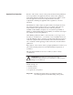
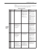
2 1336 FORCE AC Drive User Manual Page 1–6 The table has been updated to include v6.xx of the Motor Control Board. Software Compatibility MOTOR CONTROL BOARD v1.xx v2.xx v3.xx v5.xx/v6.xx Not Compatible Not Compatible Compatible with exception: ✘ Drive Comm #9–19 non–linkable. ✘ Drive Comm Tx/Rx #14–19 max value 219. ✘ Torque Stop Configuration #58 not available. ✘ Service Factor #94 not available. ✘ Feedback Device Type #150 mode 7 not available. ✘ Calculated Torque #267 not available.
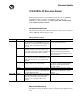
1336 FORCE AC Drive User Manual 3 Page 1–7 The table has been updated to include v6.xx of the Motor Control Board. A note was added to v5.xx of the Standard Adapter Board. MOTOR CONTROL BOARD v1.xx v2.xx v3.xx v5.xx/6.xx Compatible with exception: ✘ Drive Comm #9–19 non–linkable. ✘ Drive Comm Tx/Rx #14–19 max value 219. ✘ Torque Stop Configuration #58 not available. ✘ Service Factor #94 not available. ✘ Feedback Device Type #150 mode 7 not available. ✘ Calculated Torque #267 not available.
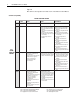
4 1336 FORCE AC Drive User Manual Pages 3–20 through 3–24 GPT information does not apply. Page 5–31 Important note added to “Drive Link Baud Rate” description.
Summary of Changes Summary of Changes Summary of Manual Changes The 5.01 release of the 1336 FORCE 5.12 User Manual contains some new and updated information. The new and updated information is summarized in the table below. For further information, refer to the page numbers provided.
This Page Intentionally Blank
Table of Contents Introduction Chapter 1 Manual Objectives . . . . . . . . . . . . . . . . . . . . . . . . . . . . . . . . . . . . . . . . . . . . . Who Should Use This Manual . . . . . . . . . . . . . . . . . . . . . . . . . . . . . . . . . . . Terminology . . . . . . . . . . . . . . . . . . . . . . . . . . . . . . . . . . . . . . . . . . . . . . . . . Standard Drive Features . . . . . . . . . . . . . . . . . . . . . . . . . . . . . . . . . . . . . . . . Performance Specifications . . . . . . . . . . . .
Table of Contents Control & Signal Wiring (PLC Comm Adapter Board) . . . . . . . . . . . . . . . . Switch Settings (PLC Comm Board) . . . . . . . . . . . . . . . . . . . . . . . . . . . . . . Discrete Outputs (PLC Comm Adapter) . . . . . . . . . . . . . . . . . . . . . . . . . . . . Discrete Inputs (PLC Comm Adapter) . . . . . . . . . . . . . . . . . . . . . . . . . . . . . Control Scheme . . . . . . . . . . . . . . . . . . . . . . . . . . . . . . . . . . . . . . . . . . . . . . .
Table of Contents Control Interface Option . . . . . . . . . . . . . . . . . . . . . . . . . . . . . . . . . . . . . . . Using the SCANport Image: . . . . . . . . . . . . . . . . . . . . . . . . . . . . . . . . . . . . I/O Image Table . . . . . . . . . . . . . . . . . . . . . . . . . . . . . . . . . . . . . . . . . . . . . . SLC to SCANport Module . . . . . . . . . . . . . . . . . . . . . . . . . . . . . . . . . . . . . Serial Communications Module . . . . . . . . . . . . . . . . . . . . . . . . . . . . .
Table of Contents Appendix Appendix A Motor Cables . . . . . . . . . . . . . . . . . . . . . . . . . . . . . . . . . . . . . . . . . . . . . . . . . Cable Termination . . . . . . . . . . . . . . . . . . . . . . . . . . . . . . . . . . . . . . . . . . . . . Enclosures . . . . . . . . . . . . . . . . . . . . . . . . . . . . . . . . . . . . . . . . . . . . . . . . . . . Derating Guidelines . . . . . . . . . . . . . . . . . . . . . . . . . . . . . . . . . . . . . . . . . . . . Drive Hardware Overview . . . .
Chapter 1 Introduction Manual Objectives The purpose of this manual is to provide the user with the necessary information to install, program, start up and maintain the 1336 FORCE Digital AC Drive. This manual should be read in its entirety before operating, servicing or initializing the 1336 FORCE Drive. Who Should Use This Manual This manual is intended for qualified service personnel responsible for setting up and servicing the 1336 FORCE AC Drive.
Chapter 1 Introduction Standard Drive Features The Bulletin1336 FORCE Field Oriented AC Drive is a microprocessor controlled Digital AC Drive with the following features: • • • • • • • • • • • • • • • • 1 to 650 HP at 0 – 250 HZ constant torque Four Quadrant operation available High Performance Digital Velocity Loop Microprocessor controlled, field oriented current loop Simplified programming through the use of a Parameter Table that features data entries in engineering units with English descriptions No
Chapter 1 Introduction • • • • Encoderless Speed Regulation – 1% of Top Speed over a 40:1 Speed Range. Accel/Decel – Independently programmable accel and decel times. Program from 0 to 6553 seconds in 0.1 second increments. Current Limit – Independent Motoring and Regenerative Limit Inverse Time Overload Capability – Class 20 protection with speed–sensitive response. Adjustable from 0–200% of rated output current in 3 speed ranges – 2:1, 4:1 & 10:1. UL Certified – Meets NEC Article 430.
Chapter 1 Introduction Environmental Specifications The following environmental guidelines apply to both the 1336 FORCE Drive and all devices and accessories connected to the Drive. • Ambient Operating Temperature: IP00, Open: 0 to 50 degrees C (32 to 122 degrees F). IP20, NEMA Type 1 Enclosed: 0 to 40 degrees C (32 to 104 degrees F). IP65, NEMA Type 4 Enclosed: 0 to 40 degrees C (32 to 104 degrees F). • Storage Temperature (all constructions): –40 to 70 degrees C (–40 to 158 degrees F).
Chapter 1 Introduction • Output Frequency Range: 0 – 250 HZ • Output Waveform: Sinusoidal (PWM) • Max. Short Circuit Current Rating : 200,000A rms symmetrical, 600 volts (when used with specified AC input line fuses as detailed in Table 2.A). • Ride Through: 2 seconds minimum • Efficiency: 97.5% at rated amps, nominal line volts • Encoder: Incremental, dual channel; 12 volts, 500mA, Supply, 5/12 Volt 10ma Min Inputs, isolated with differential transmitter, 102.5 KHz max.
Chapter 1 Introduction Software Compatibility MOTOR CONTROL BOARD v1.xx v3.xx v5.xx Not Compatible Not Compatible Compatible with exception: ✘ Drive Comm #9–19 non–linkable. ✘ Drive Comm Tx/Rx #14–19 max value 219. ✘ Torque Stop Configuration #58 not available. ✘ Service Factor #94 not available. ✘ Feedback Device Type #150 mode 7 not available. ✘ Calculated Torque #267 not available. Compatible with exception: ✘ Drive Comm #9–19 non–linkable. ✘ Drive Comm Tx/Rx #14–19 max value 219.
Chapter 1 Introduction MOTOR CONTROL BOARD v1.xx v2.xx v3.xx v5.xx Compatible with exception: ✘ Drive Comm #9–19 non–linkable. ✘ Drive Comm Tx/Rx #14–19 max value 219. ✘ Torque Stop Configuration #58 not available. ✘ Service Factor #94 not available. ✘ Feedback Device Type #150 mode 7 not available. ✘ Calculated Torque #267 not available. ✘ Precharge Timeout #225 min value 0. ✘ Perunit Motor Current #185 not available. ✘ Perunit Motor Voltage #186 not available.
Chapter 1 Introduction This Page Intentionally Blank 1–8
Chapter 2 Installation/Wiring Chapter Objectives Chapter 2 provides the information needed to properly mount and wire the 1336 FORCE Drive. Since most start–up difficulties are the result of incorrect wiring, every precaution must be taken to assure that the wiring is completed as instructed. All items must be read and understood before the actual installation begins.
Chapter 2 Installation/Wiring Figure 2.2. IP20 (NEMA Type 1) Dimensions – Frames B and C A Y Z C Max. D AA E B BB CC Mounting Holes (4) 7.0 (0.28) Knockouts (Location Will Vary with HP) 7.0 (0.28) 12.7 (0.50) 12.7 (0.50) All Dimensions in Millimeters and (Inches) All Weights in Kilograms and (Pounds) Frame 1 Reference A B C Max. D E Y Z AA BB CC Knockouts 3–Dual Size, 1–Fixed Shipping Weight B1, B2 276.4 (10.88) 476.3 (18.75) 225.0 (8.86) 212.6 (8.37) 461.0 (18.15) 32.00 (1.
Chapter 2 Installation/Wiring Figure 2.3. IP 20 (NEMA Type 1) Dimensions – Frame D A D Y Z C Max. AA E B BB Knockouts CC Mounting Holes (4) 7.0 (0.28) 7.0 (0.28) 12.7 (0.50) All Dimensions in Millimeters and (Inches) All Weights in Kilograms and (Pounds) 12.7 (0.50) Frame 1 Reference A D 381.5 (15.02) B 1240.0 (48.82) C Max. 270.8 (10.66) D 325.9 (12.83) E 1216.2 (47.88) Y 27.94 (1.10) Z 11.94 (0.47) AA 131.1 (5.16) BB 688.6 (27.11) CC 71.9 (2.83) Knockouts 3–Dual Size, 3–Fixed 62.7/76.
Chapter 2 Installation/Wiring Figure 2.4. IP 20 (NEMA Type 1) Dimensions – Frame E Z A Y C Max. D EB BB KNOCKOUTS 3–DUAL SIZE, 6–FIXED Mounting Holes (4) 7.0 (0.28) CC 7.0 (0.28) 12.7 (0.50) All Dimensions in Millimeters and (Inches) All Weights in Kilograms and (Pounds) 12.7 (0.50) Frame 1 Reference E–Enclosed E–Open 2–4 BB CC Knockouts 3–Dual Size, 6–Fixed Shipping Weight 40.1 (1.61) AA 195.0 (7.68) 901.4 (35.49) 151.9 (5.98) 88.9/101.6, 12.7 (3.50/4.00, 0.50) 186 kg (410 lbs.) 40.
Chapter 2 Installation/Wiring Figure 2.5. IP 20 (NEMA Type 1) Dimensions – Frame F 635.0 (25.00) 762.0 (30.00) 2286.0 (90.00) 252.7 (9.95) 37.9 (1.49) 193.0 (7.60) 1219.2 (48.00) 274.8 (10.82) 31.5 (1.24) 698.5 (27.50) All Dimensions in Millimeters and (Inches) Conduit Access Area 298.5 (11.75) Bottom View 50.8 (2.00) Shipping Weight 415.
Chapter 2 Installation/Wiring Figure 2.6. IP 20 (NEMA Type 1) Dimensions – Frame G Removable Lifting Angle 63.5 (2.50) 660.4 (26.00) 50.8 (2.00) (Top) 431.8 (17.00) Conduit Access Area 2324.1 (91.50) 547.6 (21.56) 431.8 (17.00) 29.0 (1.14) Conduit Access Area 254.0 (10.00) 298.5 (11.75) (Bottom) 762.0 (30.00) 635.0 (25.00) 42.9 (1.69) 381.0 (15.00) 15.9 (0.63) Dia. – 2 Mtg. Holes – All Dimensions in Millimeters and (Inches) All Weights in Kilograms and (Pounds) Shipping Weight 453.
Chapter 2 Installation/Wiring Figure 2.7. IP 20 (NEMA Type 1) Dimensions – Frame H Top Mounted Fan 635.0 (25.00) Manufacturer-dependent, may be shorter. Removable Lifting Angle 2324.1 (91.50) 762.0 (30) 508.0 (20) 635.0 (25) 1270.0 (50) 1270.0 (50) Conduit Access Area Bottom View Conduit Access Area 635.
Chapter 2 Installation/Wiring Input/Output Ratings The input and output current ratings grouped by drive voltage rating are provided in the following table: 200–240V Input Input Cat No. kVA Amps A001 2 5 A003 4–5 12 A007 10–12 28 A010 12–14 35 A015 17–20 49 A020 23–28 67 A025 25–30 73 A030 27–30 79 A040 43–51 123 A050 53–64 154 A060 60–72 174 A075 82–99 238 A100 100–120 289 A125 111–134 322 AC Supply Source 380–480V Output kVA 2 5 11 14 19 26 31 32 48 60 72 96 116 130 Output Amps 4.5 12 27.2 33.7 48.
Chapter 2 Installation/Wiring Unbalanced Distribution Systems The drive is designed for use with conventional three–phase supplies which are symmetrical with respect to ground. Surge suppression devices are included to protect the drive from lightning–induced overvoltages between line and ground. For this reason the drive must not be used directly with supplies where one phase is grounded (Grounded Delta).
Chapter 2 Installation/Wiring Input Devices Starting and Stopping the Motor ! ATTENTION: The drive start/stop control circuitry includes solid–state components. If hazards due to accidental contact with moving machinery or unintentional flow of liquid, gas or solids exist, an additional hardwired stop circuit is required to remove AC line power to the drive. When AC power is removed, there will be a loss of inherent regenerative braking effect & the motor will coast to a stop.
Chapter 2 Installation/Wiring Drive Output Disconnection Any disconnecting means wired to Drive output terminals M1, M2 and M3 must be capable of disabling the Drive if opened during Drive operation. If opened during Drive operation, the Drive will fault. It is recommended that the Drive Enable be removed before the contactor is opened. When the Drive Enable is removed, the Drive will stop modulating.
Chapter 2 Installation/Wiring Table 2.A Maximum Recommended AC Input Line Fuse Ratings (fuses are user supplied) Drive Catalog kW (HP) Rating 200–240V Number Rating UL Class CC, T, J1 – BS88 (non-UL installations) 380–480V Rating 500–600V Rating 1336T– _ _ F10 0.75 (1) 10A 6A – 1336T– _ _ F30 2.2 (3) 25A 15A – 1336T– _ _ F50 3.7 (5) 40A 20A – 1336T– _ _ 001 0.75 (1) 10A 6A 6A 1336T– _ _ 003 2.2 (3) 15A 10A 10A 1336T– _ _ 007 5.5 (7.5) 40A 20A 15A 1336T– _ _ 010 7.
Chapter 2 Installation/Wiring Electrical Interference – EMI/RFI Immunity The immunity of 1336 FORCE drives to externally generated interference is good. Usually, no special precautions are required beyond the installation practices provided in this publication. It is recommended that the coils of DC energized contactors associated with drives be suppressed with a diode or similar device, since they can generate severe electrical transients.
Chapter 2 Installation/Wiring RFI Filtering 1336 FORCE drives can be installed with an RFI filter, which controls radio–frequency conducted emissions into the main supply lines and ground wiring. If the cabling and installation recommendation precautions described in this manual are adhered to, it is unlikely that interference problems will occur when the drive is used with conventional industrial electronic circuits and systems. Also refer to “Motor Cables” in the Appendix of this manual.
Chapter 2 Installation/Wiring Grounding Refer to the grounding diagram on the following page. The drive must be connected to the system ground at the power ground (PE) terminal provided on the power terminal block (TB1). Ground impedance must conform to the requirements of national and local industrial safety regulations (NEC, VDE 0160, BSI, etc.) and should be inspected and tested at appropriate and regular intervals. In any cabinet, a single, low–impedance ground point or ground bus bar should be used.
Chapter 2 Installation/Wiring Signal Ground – TE The TE terminal block is used for all control signal shields internal to the drive. It must be connected to an earth ground by a separate continuous lead. Any PLC I/O communication link must be run in grounded steel conduit. The conduit should be bonded to ground at both ends. Ground the cable shield at the drive end only. The maximum and minimum wire size accepted by this block is 2.1 and 0.30 mm2 (14 and 22 AWG). Maximum torque is 1.36 N–m (12 lb.–in.).
Chapter 2 Installation/Wiring Power Cabling Input and output power connections are performed through terminal block TB1 on the Gate Driver Board for Frame Size B (1–15 HP, 240V; 1–30 HP, 380V; 1–20 HP, 600V) drives. For larger horsepower drives (frame sizes C,D,E,G and H), TB1 terminal blocks are located on the bottom of the drive where both the input and output power connections are to be made. Important: For maintenance and setup procedures, the drive may be operated without a motor connected. Table 2.
Chapter 2 Installation/Wiring Shielded type wire is recommended in control circuits for protection against interference. A shielded wire is required for all signal wires. The recommended conductor size must be a minimum of 16 AWG. The best interference suppression is obtained with a wire having an individual shield for every twisted pair. Figure 2.9 shows recommended cable shielding. Figure 2.9.
Chapter 2 Installation/Wiring Table 2.C Lug Selection Drive r e Catalog atalo Number AC Input R, S, T Output U, V, W and PE Cable (per Phase) T&B Part No.3 1336E–A040 1336E–A050 1336E–A060 1336E–A075 Qty. (1) (1) (1) (2) mm 2 (AWG) 1336E–A100 (2) 85.0 (3/0) 1336E–A125 (2) 107.2 (4/0) 1336E–B060 1336E–B075 1336E–B100 1336E–B125 1336E–BX150 1336E–B150 (1) (1) (1) (1) (1) (2) 42.4 (1) 53.5 (1/0) 85.0 (3/0) 107.2 (4/0) 107.2 (4/0) 53.5 (1/0) 1336E–B200 (2) 85.0 (3/0) 1336E–B250 (2) 107.
Chapter 2 Installation/Wiring Table 2.D. Cable and Wiring Recommendations Category Wiring Class Signal Definition Signal Examples Cable Type Minimum Spacing in Inches between Classes – Steel Conduit/Tray Spacing 2/3/4 5/6 7/8 9/10/11 Notes 1 Power 1 AC Power (600V or greater) 2.
Chapter 2 Installation/Wiring Power Wiring On 1 to 30 HP drives, input and output power connections are performed through a 10 position terminal block, TB1 located on the Gate Driver Board. On drives larger than 30 HP, input and output power connections are made at seperate terminal strips located at the bottom of the drive. The drive connections are illustrated in Figure 2.10.
Chapter 2 Installation/Wiring Figure 2.10. Terminal Block TB1 cont. 200–240V, 15–22 kW (20–30 HP) Terminal Designations 380–480V, 30–45 kW (40–60 HP) Terminal Designations 500–600V, 18.
Chapter 2 Installation/Wiring Figure 2.10. cont.
Chapter 2 Installation/Wiring Figure 2.10. cont. Terminal Block TB1 380-480V, 522-597 kW (700-800 HP) Terminal Designations 500-600V, 522-597 kW (700-800 HP) Terminal Designations DC + Brake H Frame T (L3) S (L2) R (L1) DC – Brake Required 1 Input Fusing U (M1) 1 Required Branch Circuit Disconnect V (M2) W (M3) AC Input Line To Motor U V (located at bottom of drive) 1 2–24 User supplied.
Chapter 2 Installation/Wiring Control Wiring ! ATTENTION: When user installed control and signal wiring with an insulation rating of less than 600V is used, this wiring must be routed inside the drive enclosure so that it is separated from any other wiring and uninsulated live parts. Failure to do so could result in equipment damage or unsatisfactory Drive performance. Encoder, Brake and Drive to Drive interface connections are performed on the Main Control Board (Fig. 2.11).
Chapter 2 Installation/Wiring Encoder Connections The Encoder connections are made at terminal block TB10 on the Main Control Board as detailed in Figure 2.12. Figure 2.12. Encoder Connections Encoder TB10 Encoder A 7 Encoder A 6 Encoder B 5 Encoder B 4 +12 Volts 3 Common 2 Shield 1 Drive to Drive Communication The TB11 connector on the Main Control Board (Figure 2.13) is used to connect the Drive to Drive Communication Interface. Figure 2.13.
Chapter 2 Installation/Wiring Figure 2.14. Drive to Drive Hardware Connection C1 . . C2 Isolator Board . 24V 1A Max .
Chapter 2 Installation/Wiring Standard Adapter Board When installing and wiring the Standard Adapter board, you need to deal with the following issues: • Control and Signal Wiring • Interface Board Installation and Removal Control & Signal Wiring – If your 1336 FORCE Drive is equipped with a Standard Adapter Board, terminal blocks TB5, TB6 and TB7 located at the bottom center of the board (Figure 2.15) are used for control and signal wiring (Drive Permissives).
Chapter 2 Installation/Wiring Interface Board Installation and Removal – IMPORTANT: If the L Option Board is being installed, Standard Adapter Board jumpers at pins 3 & 4 and 17 & 18 of J10 must be removed and the proper Input Mode selected (Figure 2.16). If the L Option board is removed, these jumpers must be reinstalled and the Input Mode parameter must be programmed to “1”. Figure 2.16. Interface Board Jumper Locations ESC SEL JOG Figure 2.17.
Chapter 2 Installation/Wiring Analog Inputs – There are (2) analog inputs to the Standard Adapter Board (Figure 2.18) that have a range of ±10V, (1) 4–20 mA analog input and (1) pulse source input with a digital resolution of 12 bits. These inputs are differential inputs with noise rejection filtering. Each input has a gain and offset adjustment. The A/D converter is a 12 bit device where an input value of +10V will result in a digital value of 2048.
Chapter 2 Installation/Wiring Analog Outputs – There are (2) analog outputs from the Standard Adapter Board that have a range of + 10V and (1) 4–20 mA output with a digital resolution of 12 bits. Discrete Outputs Fault outputs from the 1336 FORCE are supplied at terminal block TB7 on the Standard Adapter Board. Fault outputs provide warning or fault signals based on Drive Programming.
Chapter 2 Installation/Wiring Configuration The 1336 FORCE Drive is shipped pre–configured, meaning that some of the inputs and outputs are linked to a predefined signal. Figure 2.21 shows the 1336 FORCE standard configuration when equipped with a Standard Adapter Board. The user has the flexibility to configure the Drive for a particular application.
Chapter 2 Installation/Wiring Figure 2.21.
Chapter 2 Installation/Wiring Starting & Stopping the Motor ! ATTENTION: The 1336 FORCE Drive control circuitry includes solid–state components. If hazards due to accidental contact with moving machinery or unintentional flow of liquid, gas or solids exist, an additional hardwired stop circuit is required to remove AC line power to the drive. When AC input power is removed, there will be a loss of inherent regenerative braking effect and the motor will coast to a stop.
Chapter 2 Installation/Wiring Control Interface Option – TB3 The Control Interface Option provides a means of interfacing various signals and commands to the 1336 FORCE by using contact closures.
Chapter 2 Installation/Wiring Figure 2.23 provides the terminal designations for TB3. The maximum and minimum wire size accepted by TB3 is 2.1 and 0.30 mm2 (14 and 22 AWG). Maximum torque for all terminals is 1.36 N–m (12 lb.–in.). Use Copper wire only. Figure 2.23. TB3 Terminal Designations 31 32 33 34 35 36 Encoder A +12V (200mA max.
Chapter 2 Installation/Wiring Figure 2.24.
Chapter 2 Installation/Wiring Figure 2.25.
Chapter 2 Installation/Wiring Figure 2.26. Option L4/L4E Wiring L4, L4E Options Typical of Each Input 0.1µf 0.1µf 10.7k 10.7k 100 Typical NOT USED 681 Isolated +5V 5V JP4 470 0.1µf 12V 470 90.9 Isolated Ground IGND 19 20 21 22 23 24 25 26 27 28 29 30 31 A 32 33 A 34 ENC ENC 12V RET 35 36 TB3 Contacts shown are general, refer to Figure 2.24 for Input Mode selection and recommended contact types.
Chapter 2 Installation/Wiring Figure 2.27. Option L5/L5E Wiring L5, L5E Options 510 510 100 Typical 20k Typical 0.22µf NOT USED 681 5V JP4 510 12V 1k 90.9 19 20 21 22 23 24 25 26 27 28 29 30 31 A 32 33 A 34 ENC ENC 12V RET 35 36 TB3 Common User Supplied 24V AC/DC +24V Contacts shown are general, refer to Figures 2.24 & 2.25 for Input Mode selection and recommended contact types.
Chapter 2 Installation/Wiring Figure 2.28. Option L6/L6E Wiring 100 L6, L6E Options 100 20k Typical of Each Input 0.15µf 100 Typical 0.22µf NOT USED 0.33f 681 5V 499k JP4 12V 49 90.9 19 20 21 22 23 24 25 26 27 28 29 30 31 A 32 33 A 34 ENC ENC 12V RET 35 36 TB3 Common Fuse 115V AC Fuse User Supplied 115V AC Contacts shown are general, refer to Figure 2.24 for Input Mode selection and recommended contact types.
Chapter 2 Installation/Wiring PLC Communication Adapter Board Control and Signal Wiring – When installing and wiring the PLC Communication Adapter Board, you need to deal with the following issues: • Control and Signal Wiring • Jumper Settings for I/O Circuits If your 1336 FORCE Drive is equipped with a PLC Comm Adapter Board, terminal blocks TB20 & TB21 located at the bottom center of the PLC Comm Board (Figure 2.29) are used for control and signal wiring (Drive Permissives).
Chapter 2 Installation/Wiring Figure 2.30.
Chapter 2 Installation/Wiring Discrete Outputs Fault outputs from the 1336 FORCE are supplied at terminal block TB20 on the PLC Communication Adapter Board. Fault outputs provide warning or fault signals based on drive programming. Fault NC Fault Com Fault NO – A form C, NO /NC relay contact on the Standard Adapter Board programmed to provide external warning or fault change–of–state signals. Contact Ratings = 2A @ 115 VAC 2A @ 30 VDC Figure 2.31.
Chapter 2 Installation/Wiring Figure 2–33 illustrates a typical stop control scheme that might be used when the 1336 FORCE is equipped with a PLC Communication Adapter Board. For further information on PLC Communication Adapter board operation and configuration, refer to the PLC Communication Adapter Board User Manual 1336 FORCE 5.13. Figure 2.33.
Chapter 2 Installation/Wiring Configuration The 1336 FORCE Drive is shipped pre-configured, which means that some of the inputs and outputs are linked to a predefined signal. Figure 2.34 shows the 1336 FORCE standard configuration when equipped with a PLC Communication Adapter Board. The user has the flexibility to configure the Drive for a particular application. Figure 2.34.
Chapter 3 Programming Terminals Chapter Objectives Chapter 3 provides an overview of the optional Programming Terminals available for use with the 1336 FORCE Drive. The various controls and indicators found on the Human Interface Module (HIM) and the Graphic Programming Terminal (GPT) are both explained in this chapter. Additional in depth information on the Graphic Programming Terminal can be found in the GPT programming Manual.
Chapter 3 Programming Terminals Figure 3.2 HIM Front Panel LCD Display AB0273A Key Descriptions Descriptions of the keys used with the 1336 FORCE Drive are presented in the following paragraphs. Remaining keys that are not described (shaded in figure above) are not used and reserved for future use. Escape When pressed, the ESCape key will cause the programming system to go back one level in the menu tree.
Chapter 3 Programming Terminals Key Descriptions (continued) AB0285A AB0287A AB0275A Start By default, this key will initiate drive operation if hardware is enabled and no other control devices are sending a Stop command. To change this function, the [Command Mask] and [Typ 1 Logic Axis] parameters must be reconfigured. Refer to Chapter 5.
Chapter 3 Programming Terminals Module Removal For handheld operation, the module can be removed and located up to 10 meters (33 feet) from the Drive. ! ATTENTION: Some voltages present behind the Drive front cover are at incoming line potential. To avoid an electric shock hazard, use extreme caution when removing/replacing the HIM.
Chapter 3 Programming Terminals Display When selected, the Display mode allows any of the parameters to be viewed. However, parameter modifications are not allowed. Program Program mode provides access to the complete listing of parameters available for programming. Process The Process mode displays two user-selected parameters with text and scaling programmed by the user. EEPROM This mode allows all parameters to be reset to the factory default settings.
Chapter 3 Programming Terminals Program Mode or or or or or The Program mode allows access to change parameters. From the Status Display, press Enter. “Choose Mode” will be shown. Choose Mode Display Press the Increment (or Decrement) key to show “Program” if it is not currently shown. Choose Mode Program Press Enter. The Choose File Display will appear. Use the Increment (or Decrement) key to select the ‘Diagnostics’, ‘Velocity Torque’, ‘Communication I/O’ or ‘Startup’ file.
Chapter 3 Programming Terminals Display Mode or or or or The Display mode allows access to view parameters. From the Status Display, press Enter. “Choose Mode” will be shown. Choose Mode Process Press the Increment (or Decrement) key to show “Display” if it is not currently shown. Choose Mode Display Press Enter. The Choose File Display will appear. Use the Increment (or Decrement) key to select the ‘Diagnostics’, ‘Velocity Torque’, ‘Communication I/O’ or ‘Startup’ file.
Chapter 3 Programming Terminals Bit ENUMs or With drive software versions above 2.00 and a Series A (software version 3.0) or Series B HIM, bit ENUMS (16 character text strings) will be displayed to aid interpretation of bit parameters. Masks Logic Mask TB3 X1111111 Select a bit parameter with the Increment (or Decrement) keys. Press the SELect key to view the ENUM of the first bit. Pressing this key again will move the cursor to the left one bit.
Chapter 3 Programming Terminals Process Mode When selected, the Process mode will allow you to monitor 6 different pre–programmed processes. 2 of these processes can be displayed at one time. Use the Enter key to select the Process Mode. Choose Mode Process Press the Enter key again to access the Process Variable display. Process Var 1=1 Process Var 2=2 Press the Enter key again if you wish to monitor the processes under Process Variable 1.
Chapter 3 Programming Terminals EEProm Mode Reset Defaults The EEProm mode is used to restore all settings to factory default values or upload/download parameters between the HIM and drive (Series B HIM, Only). To restore factory defaults: From the Status Display, press Enter (or any key). “Choose Mode” will be displayed. Press the Increment (or Decrement) key until “EEProm” is displayed. If EEProm is not in the menu, programming is password protected. Refer to Password Mode later in this section.
Chapter 3 Programming Terminals Drive –> HIM (continued) Press Enter. An informational display will be shown, indicating the drive type and firmware version. Press Enter to start the upload. The parameter number currently being uploaded will be displayed on line 1 of the HIM. Line 2 will indicate total progress. Press ESC to stop the upload. “COMPLETE” displayed on line 2 will indicate a successful upload. Press Enter. If “ERROR” is displayed, see Chapter 6. HIM –> Drive 1336T Vector Version 3.
Chapter 3 Programming Terminals Search Mode The Search Mode is only available with a Series A (version 3.0) or Series B HIM. This mode allows you to search through the parameter list and display all parameters that are not at the factory default values. This mode also offers an option to search parameter links for links that are not factory defaults. From the Status Display, press Enter (or any key). “Choose Mode” will be shown.
Chapter 3 Programming Terminals Control Status Mode The Control Status mode is only available with a Series A (version 3.0) or Series B HIM. This mode allows the drive logic mask to be disabled, thus preventing a Serial Fault when the HIM is removed with drive power applied. The logic mask can be disabled with Series A HIM versions below 3.0 by using [Logic Mask] as explained on page 3.4. or Choose Mode Display Press the Increment (or Decrement) key until “Control Status” is displayed. Press Enter.
Chapter 3 Programming Terminals Control Status Mode (continued) Fault Queue/Clear Faults This menu provides a means to view the fault queue and clear it when desired. From the Control Status menu, press the Increment (or Decrement) key until “Fault Queue” is displayed. or Control Status Fault Queue Press Enter. Press the Increment (or Decrement) key until “View Queue” is displayed. or Press Enter. The fault queue will be displayed.
Chapter 3 Programming Terminals Control Status Mode (continued) Warning Queue/Clear Warnings This menu provides a means to view the warning queue and clear it when desired. From the Control Status menu, press the Increment (or Decrement) key until “Warning Queue” is displayed. or Control Status Warning Queue Press Enter. Press the Increment (or Decrement) key until “View Queue” is displayed. or Press Enter. The warning queue will be displayed.
Chapter 3 Programming Terminals Password Mode or The factory default password is 0 (which disables password protection). To change the password and enable password protection, perform the following steps. From the Status Display, press Enter (or any key). “Choose Mode” will be shown. Choose Mode Display Press the Increment (or Decrement) key until “Password” is displayed. Choose Mode Password Press Enter. or or Press the Increment (or Decrement) key until “Modify” is displayed.
Chapter 3 Programming Terminals Password Mode (continued) Login to the Drive or The Program/EEProm modes and the Control Logic/Clear Queue menus are now password protected and will not appear in the menu. To access these modes, perform the following steps. Press the Increment (or Decrement) key until “Password” is displayed. Press Enter. “Login” will be displayed. Press Enter, “Enter Password” will be displayed. or Press the Increment (or Decrement) key until your correct password is displayed.
Chapter 3 Programming Terminals Startup Mode or An automated Quick Startup sequence is available on the HIM to lead you through all data entry, configuration and diagnostic tests that must be performed when starting up the 1336 FORCE drive. From the Status Display, press Enter (or any key). “Choose Mode” will be shown. Choose Mode Display Press the Increment (or Decrement) key until “Startup” is displayed. Press Enter. Choose Mode Startup The “Setup Motor Nameplate” display will appear.
Chapter 3 Programming Terminals Figure 3.4 HIM Programming Steps Operator Level Power–Up and Status Display or or or or Choose Mode Mode Level Display (Read Only) Process Program (Read/Write) Link Startup Process Display Reset Defaults Drive to HIM 2 HIM to Drive 2 Recall Values Save Values Clear Links Set Links Change Process Disp3 Parameter Files EEProm Continue Reset Seq.
Chapter 3 Programming Terminals GPT Description When an optional GPT (Figure 3.5) is supplied, it will be either mounted to the front of the Drive as a panel mount terminal, or supplied as a remote device with a 1.8 meter (6 foot) long cable. The GPT offers a 40 by 8 character display that can also be used as a graphics display to show trending graphs etc. Figure 3.
Chapter 3 Programming Terminals Keypad Description The GPT keyboard (Figure 3.5) is provided as either a 26 key version (non–runtime) or 30 key (runtime version). The runtime version as shown in Figure 3.6 provides additional Start, Stop, Jog and Direction keys. Figure 3.
Chapter 3 Programming Terminals GPT Operation When power is first applied to the drive or device, a series of hardware diagnostic tests will run before the Power Up Logo Screen shown in Figure 3.7 appears. Once the initialization has been completed and all information from the drive is uploaded, the terminal will display either the Main Menu screen or the Process Display screen depending on the terminal setup information. Figure 3.
Chapter 3 Programming Terminals The Configuration option (F1 soft designator) allows you to directly access Process parameters from the Process Display screen. The Display Mode option (F3 soft designator) allows you to enter the Logo, Status or Meter modes for the Process Display parameters. IMPORTANT: Main Menu screens are dynamic and will change based on functionality provided by adapter and drive status. Figure 3.
Chapter 3 Programming Terminals Figure 3.10 GPT Programming Options Process Config Screen Process Display Screen Power Up Logo Screen Process Program Screen Main Menu Screen + INC #1 Parameter FGE Mode ❷ File DEC #2 Link Summary Sink #3 Fault Queue #4 Warning Queue Fault List Warning Entry List Source 2. Set Ref 3. Load Ref Stamp Upload Command 4. Zero Acc Element 1. Clear Warning 2. Clear Warn Q Linear Mode Numerical Parameter Screens 2. Clear Flt Q 3.
Chapter 3 Programming Terminals This Page Intentionally Blank 3–25
Chapter 4 Start–Up Introduction This chapter describes the procedure for the proper start up and tuning of the 1336 FORCE AC drive. Among the procedures you must perform in this chapter are the following: • • • • • • Pre–power checks Power–on checks Communication Configuration Parameter Programming Motor and Feedback Polarity Checks Drive Tuning and Calibration Safety Precautions ! ATTENTION: Hazard of Electric Shock exists in this drive.
Chapter 4 Startup Required Tools and Equipment ! ATTENTION: Potentially fatal voltages may result from improper useage of an oscilliscope and other test equipment. The oscilliscope chassis may be at potentially fatal voltage if not properly grounded. Allen–Bradley does not recommend use of an oscilliscope to directly measure high voltages. Use an isolated measuring device with a high voltage probe. Contact Allen–Bradley for recommendations.
Chapter 4 Startup Drive Information During Startup the following information must be recorded for reference. It is important that an accurate list of drive components be maintained and referred to when contacting service personnel. Table 4.A.
Chapter 4 Startup General Only qualified electrical technicians and/or electrical engineers familiar with solid state controls and circuitry should attempt a 1336 FORCE start–up. Figure 4.1 outlines the sequence that is required to start–up the 1336 FORCE Drive. Figure 4.1.
Chapter 4 Startup 2. Verify that the incoming power connections are properly connected and tight. Also verify that the power source is properly sized and protected for your particular drive. 3. Verify that the motor power connections are properly connected and tight. Motor Phasing should be checked, Motor Phase A should be connected to Drive output phase A, likewise Phase B and C should be properly terminated to their respective terminals. This phasing will be double checked later in this procedure. 4.
Chapter 4 Startup Startup Configuration Procedures After you have completed all wiring and power up the drive, the parameter configuration procedure must be completed using one of the Startup Configuration Procedures (Quick, or Manual). The configuration procedures used here assumes you have a HIM programming terminal and a Standard Adapter Board in your Drive.
Chapter 4 Startup Quick Start Procedure or or 1. An automated Quick Startup sequence is available on the HIM to lead you through all data entry, configuration and diagnostic tests that must be performed when starting up the 1336 FORCE drive. From the Status Display, press Enter (or any key). “Choose Mode” will be shown. Choose Mode Display Press the Increment (or Decrement) key until “Startup” is displayed. Press Enter. Choose Mode Startup The “Setup Motor Nameplate” display will appear.
Chapter 4 Startup Quick Start Procedure cont. 1. After Inverter Diagnostics has concluded, or if you answer NO to the Motor Connect Diagnostics question, a display will appear asking if you wish to run the Autotune Torque & Velocity sequence. Autotune Torque & Vel Loops Y Press the Enter key to initiate the test. If you answer YES to the Autotune Torque & Velocity question, the following configuration options will appear in sequence as each configuration operation is completed. 1. Measure Parameters 2.
Chapter 4 Startup Quick Start Procedure cont. If you answer NO to the Autotune Torque & Velocity question, the following configuration options will appear in sequence as each configuration operation is completed 1. Configure I/O? 2. Configure Scanport? 3. Configure Input Mode? 4. Configure Pulse Input? 5. Configure MOP? 6. Configure Analog Input? 7. Configure Analog Output? Use the SELect key to access the 2nd line in any configuration display, and the INC or DEC keys to make any changes.
Chapter 4 Startup Manual Startup Mode or Drive Mode Menu Press the ESC key to access the Drive Mode Menu. The Choose Mode display should appear as shown below: Use the INC/DEC keys to scroll thru the Drive Mode menu selections until the PROGRAM selection is reached. Press the ENTER key to enter the Program Mode. The HIM display should appear as shown below: Choose MODE Program Use the INC/DEC keys to select the Startup File.
Chapter 4 Startup NOTE: It is important that you retain a record of the feedback device that was selected, because the bandwidth of the velocity regulator will be significantly reduced when the drive is used without an encoder. AB0270A After the feedback device type has been selected and accepted, press the ESC key to return to the Startup Menu.
Chapter 4 Startup • Motor Poles – Number of Motor Poles (Nameplate) • Undervoltage Setpoint – Sets minimum threshold voltage for a Bus undervoltage condition. Should be set to a value of 200V for 230V AC drives, and 400V for a 460VAC drive. • Torque Mode Select – This parameter is used to select the source for the drive torque reference.
Chapter 4 Startup Limits Menu Selections: Fwd Speed Limit 1750 RPM Use the INC/DEC keys to scroll through the Limits menu selections. or AB0282A Blinking First then Blinking or AB0270A When you reach the Limit selection that you wish to change, press the SEL key to move the blinking cursor down to the value field.
Chapter 4 Startup AB0282A or Scroll to the Autotune Diag Sel parameter. Set Bit 0 to a value of 1, and then press the ENTER key and the START button. This will execute the Inverter Transistor Diagnostics test which will take 300 mSec to run. Bit 0 will automatically be set back to 0 upon successful completion of the Inverter Transistor Diagnostics test. If the test fails (non–zero value with flashing CP or VP light), refer to the Startup troubleshooting section of this manual (Chap 6).
Chapter 4 Startup AB0282A or After the Phase Rotation test has been performed, and the motor rotates in the positive direction with positive encoder feedback, you are ready to tune both the Torq Loop and Velocity Loop of the Drive. Tuning both the Torq & Velocity loops requires setting bits 2 thru 8 to a value of 1 and then pressing ENTER followed by pressing the START key on the HIM.
Chapter 4 Startup or AB0287A After the New Values for Kp & Ki have been calculated, you are now ready to start the Drive in Velocity mode. Before starting the Drive, use the INC/DEC keys to scroll to Vel Feedback in the Drive Tune Menu. Start the Drive by pressing the START key on the HIM. Press the SPEED INCREMENT key to slowly increment the velocity reference. Observe velocity feedback and motor shaft rotation making sure both are stable.
Chapter 4 Startup Communication Configuration Drive to Drive Communication – Drive to Drive Communication (D2D) provides high speed communications between drives. D2D is capable of connecting up to 64 Drives together using three different transfer rates, 125K (64 nodes), 250K (64 nodes), and 500K (32 nodes) baud. Hardware Setup – Refer to Chapter 2 Installation for Drive to Drive wiring, L Option wiring and Pulse Input Configuration.
Chapter 4 Startup Message Transfer – The D2D allows each drive to transfer two words and receive two words from two different drives for a total words received of four (Figure 4.3). Figure 4.3.
Chapter 4 Startup Receiver Example: P16 Drive Receive Indirect 1 – Any VP/CP Parameter or – P22 (Receive 1, Data 1) P22 would then have a value or a non VP/CP parm linked to it. Data – The D2D TX and RX data exists as non VP parameters in the parameter table. This allows data outside the Motor Control Board to get access to the D2D. Data parameter examples were shown in the previous transmitter and receiver examples. Master/ Slave Drive to Drive Communication – Figure 4.
Chapter 4 Startup The slave drive is set up by first setting P12 (Drive Receive 1 Address). P12 contains the address of the tranmitter that you wish to receive data from. In this example, a value of 1 is entered, indicating that data should be read from transmitter 1. P16 (Drive Receive Indirect 1) should be set to P101 (Ext Vel Ref). It should be noted that the typical transmission time from the master to the slave is between 4ms to 6ms using links, otherwise using indirects it is only 2ms to 4ms.
Chapter 4 Startup 4. The NORMAL STOP (TB20 terminal 3) input is stop command that will stop the drive according to the specified Stop Mode. The drive responds the same way it would if the STOP bit were set in any Logic Command. The red LED D7 reflects the present state of the STOP input. When a Stop is in effect the LED is illuminated and the Drive is not allowed to run. 5. The FAULT OUT (TB20 terminals 8,9,10) input is a Form C relay contact. Red LED D4 reflects the status of relay contact.
Chapter 4 Startup Figure 4.7.
Chapter 4 Startup Analog I/O Parameter Configuration: When you have accomplished the hard wiring of the Analog I/O to the Standard Adapter Board terminals as was detailed in Chapter 2, it is still necessary to set up the parameters in the Drive to allow for data flow between the Adapter Board and the Drive. Each Input/Output has parameters associated with it as shown in Figure 4.7. Set-Up parameters are used to program the Standard Adapter Board functions, such as Scale and Offset.
Chapter 4 Startup A 10V Input and a Pot Input will be used in detailing the scaling and offset parameters. At Pot Input, between TB5 terminals 7 and 8, a potentiometer with a range of ±10V DC has been connected. Parameter 358 has been linked to Parameter 104 (Velocity Reference 2 HI) in the Drive, which gives the potentiometer control of the external velocity reference. To calibrate the pot to control 100% base speed in both directions, the scaling parameter must be adjusted.
Chapter 4 Startup As shown in Figure 4.9, the offset voltage adds the corresponding digital value to the range. In this case, an offset of –5 volts adds a digital value of –1024 to the range. This causes 0 volts on the potentiometer to register as –1024 digital internal to the drive and 10 volts on the potentiometer will be +1024 to the drive.
Chapter 4 Startup In Figure 4.10 Analog Output 1 is used as an example to detail the scaling and offset parameters. At Analog Output 1 a meter with a range of 0-10 V DC has been connected. Parameter 370 has been linked to Parameter 146 (Velocity Feedback). In order for the meter to indicate speed in both directions, the scale and offset parameters must be adjusted as shown in Figure 4.10. Working in the opposite direction as the analog inputs, apply the scale factor first.
Chapter 4 Startup SCANport Analog I/O Parameter Configuration: SCANport analog I/O is what is received from and sent to the SCANport devices. Figure 4.11.
Chapter 4 Startup The programmable relay is a normally open contact and is configured through the Output Select parameter 384. It allows the relay to follow a single bit within the Logic Status parameters 56 and 57. The relay can be configured to follow the bit function or the not of the bit function. For Example; When the motor is at set speed and you wish the contact to close, you must enter AT SET SPEED (8).
Chapter 4 Startup SCANport Control Configuration: The SCANport controls are the functions that control the motor, like start, stop, jog etc. The control can come from up to 6 SCANport devices and L Option Inputs at the same time. The control is based on a ownership mechanism which allows certain functions to have only one owner and other functions to have multiple owners. Speed reference, direction and local functions are the only one owner functions. The other functions like start, stop, jog etc.
Chapter 4 Startup option only, based on the stop type in modes 3, 13 and 16. Stop from SCANport devices follow parameter 59 bits 4 & 5. The Accel Rates (389 & 390) and Decel Rates (391 & 392) are selected by modes 4, 11 and 14. NOTE: Mode 2, 3, 4, 5 and 6 take permanent ownership of the direction function. NOTE: If the Control Interface Option is other than 1, the Control Interface Option speed reference will take ownership of the speed reference.
Chapter 4 Startup Within the 1336 FORCE drive, the I/O image table resembles the following: Logic Command Word (parameter 52) Bit 0 Normal Stop Bit 1 Start➀ Bit 2 Jog 1➀ Bit 3 Clear Fault Bit 4 Forward Bit 5 Reverse Bit 6 Jog 2➀ Bit 7 Cur Lim Stop Bit 8 Coast Stop Bit 9 Spd Ramp Dis Bit 10 Flux Enable Bit 11 Process Trim Bit 12 Speed Ref A Bit 13 Speed Ref B Bit 14 Speed Ref C Bit 15 Reset Drive Logic Status LOW (parameter 56) Bit 0 Run Ready Bit 1 Running Bit 2 Command Dir Bit 3 Rotating Dir Bit 4 Accele
Chapter 4 Startup SLC to SCANport Module: The following figure shows how the I/O image table for the SLC programmable controller relates to the 1336 FORCE drive. In this example, the drive is connected to channel 1 of the SLC module in enhanced mode. If this were an example of basic mode, only the O:1.2, O:1.3, I:1.2, and I:1.3 entries would be used.
Chapter 4 Startup Serial Communications Module: The following figure shows how the I/O image table for the programmable controller relates to the 1336 FORCE drive when a Serial Communications Module is used.
Chapter 4 Startup Remote I/O Communications Module: The following figure shows how the I/O image table for the programmable controller relates to the 1336 FORCE drive when a Remote I/O Communications Module is used.
Chapter 4 Startup This Page Intentionally Blank 4–35
Chapter 5 Programming Parameters Introduction This chapter contains the information required to assist you in programming the 1336 FORCE AC Drive for a specific application after initial start–up. Drives are shipped programmed with default values and are preconfigured for the options installed. Parameters 0 thru 288 are the parameters for the 1336 FORCE Motor Control Board. Parameters 300 and above cover the Adapter Board of the 1336 FORCE DRIVE.
Chapter 5 Programming Parameters Engineering Units – A label given to parameter data which specifies what units are to be used to display the parameter value on the Programming Terminal. Examples of engineering units include: RPM, % etc. Non–Volatile Memory – Data memory in the drive which retains the values of all data even when power is disconnected from the drive control. BRAM (Battery Backed Random Access Memory) chips are used for the non–volatile memory to store some of the drive parameters.
Chapter 5 Programming Parameters Parameter Table (Standard Adapter Equipped Drives) Note: For PLC Comm equipped drives refer to your PLC Comm User Manual for parameter descriptions. For ControlNet Adapter equipped drives, refer to your ControlNet Adapter Manual for parameter descriptions. Table 5.A – 1336 FORCE Numerical Parameter Table Param No.
Chapter 5 Programming Parameters Table 5.A – 1336T Numerical Parameter Table (Cont.) Param No.
Chapter 5 Programming Parameters Table 5.A – 1336T Numerical Parameter Table (Cont.) Param No.
Chapter 5 Programming Parameters Table 5.A – 1336T Numerical Parameter Table (Cont.) Param No.
Chapter 5 Programming Parameters Table 5.A – 1336T Numerical Parameter Table (Cont.) Param No. Parameter Name (Element) 172 Torque Reference Testpoint Data 173 Torque Reference Testpoint Select 174 Minimum Flux Level 175 Pos Torque Reference Limit 176 Neg Torque Reference Limit 177 Motoring Power Limit 178 Regen.
Chapter 5 Programming Parameters Table 5.A – 1336T Numerical Parameter Table (Cont.) Param No.
Chapter 5 Programming Parameters Table 5.A – 1336T Numerical Parameter Table (Cont.) Param No.
Chapter 5 Programming Parameters Table 5.A – 1336T Numerical Parameter Table (Standard Adapter Parameters) Param No.
Chapter 5 Programming Parameters Table 5.B – 1336T Alphabetical Parameter Table Parameter Name (Element) Param No. Absolute Overspeed Threshold Accel Rate 1 Accel Rate 2 Accel Time Adapter Config.
Chapter 5 Programming Parameters Table 5.B – 1336T Alphabetical Parameter Table 5–12 Parameter Name (Element) Param No. Page Ref.
Chapter 5 Programming Parameters Table 5.B – 1336T Alphabetical Parameter Table Parameter Name (Element) Kp Frequency Regulator Kp Slip Regulator Kp Velocity Loop Ksel Freq.
Chapter 5 Programming Parameters Table 5.
Chapter 5 Programming Parameters Table 5.
Chapter 5 Programming Parameters Table 5.B – 1336T Alphabetical Parameter Table Parameter Name (Element) Param No. Page Ref.
Chapter 5 Programming Parameters Figure 5.2. Standard Adapter Parameters (cont.
Chapter 5 Programming Parameters Figure 5.2. Standard Adapter Parameters (cont.
Chapter 5 Programming Parameters Figure 5.2. Standard Adapter Parameters (cont.
Chapter 5 Programming Parameters PLC Comm Adapter Parameters If your 1336 FORCE Drive is equipped with a PLC Comm Adapter Board, the parameters in the range from 300 to 500 are dedicated exclusively to the PLC Comm Adapter Board rather than the Standard Adapter Board. PLC Comm Adapter Parameters are divided into four files as they are with a Standard Adapter Board equipped Drive. The complete parameter table for a PLC Comm Adapter equipped 1336 Force is detailed in Figure 5.3.
Chapter 5 Programming Parameters Figure 5.3. PLC Comm Adapter Parameters (cont.
Chapter 5 Programming Parameters Figure 5.3. PLC Comm Adapter Parameters (cont.
Chapter 5 Programming Parameters Figure 5.3. PLC Comm Adapter Parameters (cont.) FILE 4 – Diagnostics Monitor 8 147 148 149 167 168 182 185 186 264 265 266 268 269 270 271 Motor Control Counter Scaled Velocity Fdbk Enc Pos Fdbk Lo Enc Pos Fdbk Hi Internal Torque Fdbk Internal Iq Ref Computed Power Perunit Motor Current Perunit Motor Voltage Motor I Magn. Fdbk Motor Volt Magn.
Chapter 5 Programming Parameters ControlNet Parameters The complete parameter table for a ControlNet Adapter Board equipped 1336 FORCE is detailed in Figure 5.4. The table has been divided into Files, Groups & Elements for ease of reference. For a detailed description of ControlNet parameters, refer to the ControlNet Adapter Reference Manual. Figure 5.
Chapter 5 Programming Parameters File 2 – Communications I/O Channel A Group Logic Group CntrlNet In 0 322 ChA Logic Cmd In CntrlNet In 1 323 Logic Command CntrlNet In 2 324 CntrlNet In 3 325 CntrlNet In 4 326 CntrlNet In 5 327 CntrlNet In 6 328 CntrlNet In 7 CntrlNet Out 0 Analog Input Group Analog Output Group Analog In 1 339 Analog Out 1 387 52 An In 1 Offset 392 An Out 1 Offset 400 Logic Status Low 56 An In 1 Scale 393 An Out 1 Scale 401 Logic Status Hi 57 Analog I
Chapter 5 Programming Parameters File 3 – Velocity Torque➀ Velocity Ref Logic Preset Speed 1 119 ChA Logic Cmd In Preset Speed 2 120 Preset Speed 3 121 Preset Speed 4 Velocity Fdbk 367 Filt Vel Fdbk Logic Command 52 Torq Stop Confg 58 122 Logic Options Preset Speed 5 123 Jog Speed 1 Velocity Reg Torque Ref 269 Vel Reg Output 134 Torque Mode Sel 53 Vel Feedback 146 Ki Velocity Loop 139 Torq Mode Stat 184 Scaled Vel Fdbk 147 Kp Velocity Loop 140 Pos Mtr Cur Lmt 179 59
Chapter 5 Programming Parameters Torque Block➀ Process Trim Torque Autotune Velocity Autotune PWM Frequency 222 Proc Trim Ref 27 Autotun Diag Sel 256 Autotun Diag Sel 256 Prech Rdthru Sel 223 Proc Trim Fdbk 28 Ph Rot Cur Ref 262 Auto Tune Torque 40 Under Volt Stpnt 224 Proc Trim Output 26 Auto Tune Torque 40 Auto Tune Speed 41 Prechrg Timeout 225 Proc Trim Select 29 Auto Tune Speed 41 Total Inertia 46 Ridethru Timeout 226 Proc Trim Ki 32 Ph Rot Freq Ref 263 Motor I
Chapter 5 Programming Parameters File 4 – Diagnostics➀ Monitor Testpoints Fault Sel/Sts Filt Vel Fdbk 269 Vel Fdbk TP Sel 145 SP Fault Sts Scaled Vel Fdbk 147 Vel Fdbk TP Low 143 Int Torque Ref 167 Vel Fdbk TP Hi 144 Internal Iq Ref 168 Vel Reg TP Sel Computed Power 182 DC Bus Voltage 268 Motor Volt Fdbk 265 Motor Curr Fdbk 264 Freq Command Motor Overload 442 Mtr Overload Lim 92 SP Warn Sts 443 Mtr Overld Spd 1 95 SP Fault Sel 440 Mtr Overld Spd 2 96 137 SP Warn Sel
Chapter 5 Programming Parameters Transistor Diag➀ Autotun Diag Sel Trend I/O Trend Setup Info 256 Tr1 Status 462 Tr1 Opnd Parm X 455 Drive SW Version 59 Tr2 Status 472 Tr1 Opnd Parm Y 456 Drive Type Tran Diag Disabl 257 Tr3 Status 482 Tr1 Operator 457 Base Drive Curr 220 Inverter Diag 1 258 Tr4 Status 492 Tr1 Sample Rate 458 Base Line Volt 221 Inverter Diag 2 259 Trend In 1 454 Tr1 Post Samples 459 Adapter Version 301 Iq Offset 260 Trend In 2 464 Tr1 Cont Trigger
Chapter 5 Programming Parameters Parameter Descriptions A detailed description of each 1336 FORCE Parameter is contained in the following listing. The parameters are listed in numerical order. Take note that some parameters are used more than once in the 1336 FORCE, and may be located in more than one File and Group. To determine if a parameter is used in more than one application, refer to the numerical list which begins on Page 5-3.
Chapter 5 Programming Parameters Drive Software Version [Drive SIO Version] This parameter stores the present software revision for the firmware product. The firmware value represents the software version in the range 00.0 to 99.9. Power Structure Type [Drive Type] This number is a unique code that identifies the drive’s current and voltage ratings. This number originates from a serial EE memory located on the Drive’s Base Drive Board.
Chapter 5 Programming Parameters Drive Link Receive 2 Address [D2D Rcv 2 Addr] This parameter specifies the node address at which two words of data will be received. A value of zero disables the receive function. Drive Link Transmit Indirect 1 [D2D Xmit Ind 1] This is a word parameter defining the parameter number which data will be fetched from to be transmitted in the high speed communication network (CAN) for the first word location of the transmitted message.
Chapter 5 Programming Parameters Drive Link Transmit Data 1 [D2D Xmit Data1] This parameter is the default data location of the first word of data for transmit. Drive Link Transmit Data 2 [D2D Xmit Data2] This parameter is the default data location of the second word of data for transmit.
Chapter 5 Programming Parameters Process Trim Reference [Proc Trim Ref] This is the reference input value for process trim. The Process Trim Output is updated based on the value of this input. Process Trim Feedback [Proc Trim Fdbk] This is the feedback input value for process trim. The Process Trim Output parameter is updated based on the value of this input.
Chapter 5 Programming Parameters Process Trim KP Gain [Proc Trim Kp ] This parameter controls the proportional gain of the process trim regulator. If the KP process trim is equal to 1.0, then the process trim PI regulator output will equal 1 pu for 1 pu process trim error. Process Trim Low Limit [Proc Trim Lo Lmt] The output of the process trim regulator is limited by adjustable high and low limits. This parameter specifies the low limit of the process trim output value.
Chapter 5 Programming Parameters Auto Tune Speed [Auto Tune Speed] This parameter is the speed of the motor during an auto tune velocity motor test, system test, and system ID measure. 4096 is base speed VP Desired Bandwidth [Vel Desired BW] This parameter specifies the velocity loop bandwidth requested by the User and determines the dynamic behavior of the velocity loop. The maximum value for this parameter is changed by the drive when a request is made to update the the velocity loop gains.
Chapter 5 Programming Parameters Auto Tune Testpoint Select [Auto Tune TP Sel] This parameter selects what internal location of the Velocity Auto Tune Controller will become the testpoint value shown in P47.
Chapter 5 Programming Parameters Local Input Status [Local In Status] Parameter Number Parameter Type Display Units Drive Units Factory Default Minimum Value Maximum Value Enums: This parameter indicates boolean input status conditions for the Velocity Processor. When a bit is set to 1, the corresponding input signal is true.
Chapter 5 Programming Parameters Torque Stop Configuration [Torq Stop Config] This parameter selects how the drive will react to a stop command when it occurs in a non–speed mode (ex. torque mode). Possible selections are: 0 = Normal Mode – Switch to speed mode. then perform a controlled stop. 1 = Stay in selected torque mode until zero speed is reached. 2 = Stay in selected torque mode until zero torque is reached.
Chapter 5 Programming Parameters Over Setpoint 3 [Over Setpoint 3] This parameter is used to specify the setpoint threshold for the Over Setpoint 3 bit in Logic Status Hi. Over Setpoint 4 [Over Setpoint 4] This parameter is used to specify the setpoint threshold for the Over Setpoint 4 bit in Logic Status Hi. Parameter Number Parameter Type Display Units Drive Units Factory Default Minimum Value Maximum Value 64 Sink +/– x.x% 4096 = 100.0% setpoint +0.0 % –800.0% +800.
Chapter 5 Programming Parameters Logic Testpoint Select [Logic Tstpt Sel] Parameter Number Parameter Type Display Units Drive Units Factory Default Minimum Value Maximum Value Enums: This parameter selects which internal location in the logic control software will become the testpoint value shown in P70. The value based upon the select will be stored in the Logic Tstpnt Data parameter.
Chapter 5 Programming Parameters Powerup/Diagnostic Fault Status [PwrUp Flt Status] This word parameter indicates a fault condition which has been detected during power up or reset of the drive. When a bit is “1”, the condition is true, otherwise the condition is false. Bit 0 1 2 3 4 5 6 7 8 This word parameter indicates fault conditions in the drive that Cannot be configured as warnings. When a bit is “1”, the condition is true, otherwise the condition is false. Bits 0 – 3 are detected by hardware.
Chapter 5 Programming Parameters CP Configurable Warning Status [CP Warn Status] This word parameter indicates conditions detected by the current processor (CP) that have been configured to report as a Drive Warning condition. Each configuration bit matches the bit definitions of parameters 82, 86 and 87. When a bit is set to “1” the corresponding condition in the Drive is true, otherwise it is false.
Chapter 5 Programming Parameters CP Warning/None Configuration Select [CP Warn Select] Parameter Number Parameter Type Display Units Drive Units Factory Default Minimum Value Maximum Value Enums: 87 Sink Bits None 0000 0000 0001 1111 0000 0000 0000 0000 1111 1111 1111 1111 Parameter Number Parameter Type Display Units Drive Units Factory Default Minimum Value Maximum Value Enums: 88 Sink Bits None 1111 1111 1111 1111 0000 0000 0000 0000 1111 1111 1111 1111 This word parameter determines conditions det
Chapter 5 Programming Parameters Absolute Overspeed Threshold [Absolute Overspd] This parameter indicates the incremental speed above Forward Speed Limit or below Reverse Speed Limit that is allowable before an Absolute Overspeed Fault is indicated. Stall Delay [Stall Delay] This parameter specifies the amount of time that the Drive must be in current limit and at zero speed before a Stall Fault will be indicated.
Chapter 5 Programming Parameters Fault Testpoint Data [Fault TP] This parameter contains the fault control testpoint data that has been selected by the Fault TP Sel parameter(P99). See the description for the Fault TP Sel parameter 99 for a list of possible testpoints. Fault Testpoint Select [Fault TP Sel] This parameter selects which internal location in the fault control software will become the testpoint value. The value based upon the selection will be stored in the Fault TP parameter 98.
Chapter 5 Programming Parameters Velocity Reference 2 LOW (Fraction) [Vel Ref 2 Low] This word supplies the fractional part of the external velocity reference 2 when the external velocity control has been selected in Logic Command (P52).
Chapter 5 Programming Parameters Velocity Reference Testpoint Select [Vel Ref TP Sel] This parameter selects which internal location of the velocity reference will become the testpoint value shown in P108 and 109.
Chapter 5 Programming Parameters Preset Speed 4 [Preset Speed 4] This will be the velocity reference used by the Drive when preset 4 has been selected in the Logic Command (P52). Preset Speed 5 [Preset Speed 5] This will be the velocity reference used by the Drive when preset 5 has been selected in Logic Command (P52). Accel Time [Accel Time] This parameter displays the ramp rate time for the velocity reference ramp. Time is seconds from zero to base motor speed. Zero will disable accel ramp.
Chapter 5 Programming Parameters Maximum Forward Speed Trim [Max Fwd Spd Trim] This parameter limits the maximum value of the velocity reference after the process trim. Droop Percent [Droop Percent] This parameter specifies the percent of base speed that the velocity reference will be reduced when at full load torque. This feature can be used to cause motor velocity to droop with an increase in load.
Chapter 5 Programming Parameters Velocity Regulator Testpoint Select [Vel Reg TP Sel] Parameter Number Parameter Type Display Units Drive Units Factory Default Minimum Value Maximum Value 137 Sink x None 0 0 15 Parameter Number Parameter Type Display Units Drive Units Factory Default Minimum Value Maximum Value 138 Source +/– x.x rpm 4096 = Base Motor Speed +0.
Chapter 5 Programming Parameters Velocity Feedback Testpoint Data LOW Parameter Number [Vel Fdbk TP Low) Parameter Type Display Units This parameter contains the LOW part of Drive Units the 32 bit value of the internal location selected by the Vel Fdbk Factory Default TP Sel Parameter, P145.
Chapter 5 Programming Parameters Encoder Position Feedback LOW [Enc Pos Fdbk Low] This is the LOW word portion of a 32 bit encoder pulse accumulator. Each encoder quadrature edge will be counted, resulting in a 4X multiplication. As a result, this parameter will be scaled such that the position change per motor revolution is equal to 4 times the encoder PPR.
Chapter 5 Programming Parameters Tach Velocity [Tach Velocity] This word supplies a motor velocity feedback signal when a source other than an encoder is used. This input will typically be linked to an analog input parameter from the adapter board. Notch Filter Frequency [Notch Filt Freq] This parameter sets the center frequency for an optional 2–pole notch filter. Thenotch filter is enabled by selecting a value of ‘4’ in parameter 152.
Chapter 5 Programming Parameters External Torque Step [Ext Torque Step] This parameter supplies an external torque offset to the Drive. The Ext Torque Step is summed with the Torque Mode Sel (P53) output prior to the Torque Limiter. Internal Torque Reference [Int Torque Ref] This parameter shows the value of torque reference that is present at the output of the torque limiter.
Chapter 5 Programming Parameters Minimum Flux Level [Min Flux Level] This parameter sets the smallest level of flux that will be used to convert a torque to a current reference. Setting the parameter to 4096 will prevent flux reduction and bypass the torque to current conversion. Pos Torque Reference Limit [Pos Mtr Tor Lmt] This parameter provides a user settable torque limit for positive torque reference values. Positive motor torque reference will not be allowed to exceed this value.
Chapter 5 Programming Parameters Di/DT Limit [Di/Dt Limit] This parameter determines the largest allowable rate of change for the Iq reference signal. This number is scaled in units of maximum per unit Iq every 2 msec. Computed Power [Computed Power] Calculated product of Torque Reference time motor velocity feedback. A 125 msec filter is applied to this result. Positive values indicate motoring power, negative regenerative power.
Chapter 5 Programming Parameters Parameter Number Parameter Type Displays the perunit value of motor voltage Display Units Drive Units as determined from an analog–to–digital converter input. This data is scaled to read Factory Default 1.0 pu at rated motor voltage. This is a Minimum Value version of parameter 265 that has been Maximum Value 186 Source x.x% 4096 = 100.0% motor voltage 0.0% 0.0% 800.
Chapter 5 Programming Parameters Precharge/Ridethru Selection [Prech/Rdethru Sel] Parameter 223 lets you choose options for the bus filter reference, precharge/ridethrough conditions, and braking. Use bits 0 through 4 to set the slew rate for the bus voltage tracker. The bus voltage tracker slowly tracks changes in the actual bus voltage. If none of the bits (0 through 4) are set, the slew rate is 0.05V/second.
Chapter 5 Programming Parameters CP Operating Options [CP Options] For proper operation, bits 0 to 6 must be left at zero. If bit 7 = 0, this allows the motor to coast to a stop after the flux test is completed. If bit 7 = 1, this brings the motor to a controlled stop after the flux test is completed. Motor Nameplate Horsepower [Base Motor HP] User entered value of nameplate motor horsepower. The drive uses this information in the Dynamic Brake Resistor temperature calculation.
Chapter 5 Programming Parameters Encoder PPR [Encoder PPR] User entered pulse per revolution rating of the feedback device when using an encoder to determine motor velocity.
Chapter 5 Programming Parameters Vqe Maximum (Constant HP) [Vqe Max] Q axis voltage at which the motor enters field weakening. Parameter calculated by autocommissioning routine and MUST NOT BE CHANGED. Data represented as x.x volts Vde Minimum (Constant HP) [Vde Min] D axis voltage below which the adaption to motor changes in the torque control is disabled. Parameter calculated by autocommissioning routine and MUST NOT BE CHANGED. Data represented as x.
Chapter 5 Programming Parameters Ki – Regulator [Ki Flux] Integral gain of the slip regulator This parameter MUST NOT BE CHANGED. Data represented as x.
Chapter 5 Programming Parameters Inverter Diagnostics Result #2 [Inverter Diag 2] Parameter Number Parameter Type Display Units The results of the Transistor Diagnostic Drive Units Tests are given in parameters 258 & 259. If any of the bits shown below are set, then Factory Default a problem with the associated test is Minimum Value indicated.
Chapter 5 Programming Parameters Stator Frequency [Freq Command] Displays the actual value of motor stator frequency. Units are in Hz times 128 (128 @ 1 Hz) Parameter Number Parameter Type Display Units Drive Units Factory Default Minimum Value Maximum Value Calculated Torque [Calc Torque] 266 Source x .xxx Hz 128 @ 1Hz 0 .000 Hz –255.992 Hz +255.
Chapter 5 Programming Parameters Testpoint Data #1 [Torq TP Sel 1] This parameter contains the data selected by Testpoint Selection #1 (param 273). Testpoint Selection #2 [Torq TP Sel 2] This parameter selects a torque block test point. The value of that test point can be read from Testpoint Data #2 (Parm 276). Testpoint Data #2 [Torq TP Data 2] This parameter contains the data selected by Testpoint Selection #1 (param 275).
Chapter 5 Programming Parameters Testpoint Selection #5 [Torq TP Sel 5] This parameter selects a torque block test point. The value of that test point can be read from Testpoint Data #5 (Parm 282). Testpoint Data #5 [Torq TP Data 5] This parameter contains the data selected by Testpoint Selection #5 (param 281). Testpoint Selection #6 [Torq TP Sel 6] This parameter selects a torque block test point. The value of that test point can be read from Testpoint Data #6 (Parm 284).
Chapter 5 Programming Parameters Kp Frequency Regulator [Kp Freq Reg] Proportional gain of the frequency regulator in sensorless mode. This parameter must not be changed. Kff Freq Regulator [Kff Freq Reg] Feedforward gain of the frequency regulator in sensorless mode. This parameter must not be changed. Ksel Freq Regulator [Ksel Freq Reg] Low frequency gain boost of the frequency regulator in sensorless mode. This parameter must not be changed.
Chapter 5 Programming Parameters Motor Inductance Test Errors [Lo Test Error] This parameter indicates an error condition detected during the motor inductance test.
Chapter 5 Programming Parameters NOTE: The Parameters shown here in the range from 300 to 500 are Standard Adapter Parameters Only! Parameter descriptions for PLC Comm Adapter Parameters are covered in the PLC Comm Adapter User Manual. Adapter Identification Number [Adapter ID] This parameter displays the Standard Adapter ID. Adapter Software Version [Adapter Version] This parameter displays the software version number.
Chapter 5 Programming Parameters Data In B2 [Data In B2] This parameter displays the SCANport to drive image which is received from some device on SCANport. Data In C1 [Data In C1] This parameter displays the SCANport to drive image which is received from some device on SCANport. Data In C2 [Data In C2] This parameter displays the SCANport to drive image which is received from some device on SCANport.
Chapter 5 Programming Parameters Data Out B2 [Data Out B2] This parameter displays the drive to SCANport image which is sent to some device on SCANport Data Out C1 [Data Out C1] This parameter displays the drive to SCANport image which is sent to some device on SCANport Data Out C2 [Data Out C2] This parameter displays the drive to SCANport image which is sent to some device on SCANport Data Out D1 [Data Out D1] This parameter displays the drive to SCANport image which is sent to some device on SCANport
Chapter 5 Programming Parameters SCANport Direction Mask [Direction Mask] This parameter selects which SCANport devices can issue a forward/reverse command. 1 = Permit Control 0 = Deny Control Bit 0 – TB3 Bit 1 – SCANport Device 1 Bit 2 – SCANport Device 2 Bit 3 – SCANport Device 3 Bit 4 – SCANport Device 4 Bit 5 – SCANport Device 5 SCANport Start Mask [Start Mask] This parameter selects which SCANport devices can issue a start command.
Chapter 5 Programming Parameters SCANport Reset Drive Mask [Reset Drive Mask] Parameter Number Parameter Type Display Units This parameter selects which SCANport devices can issue a Reset Drive command.
Chapter 5 Programming Parameters SCANport Jog 1 Owner [Jog 1 Owner] This parameter displays which SCANport devices are presently issuing a valid jog 1 command. 1 = Jog 1 Input present 0 = Jog 1 Input Not Present Bit 0 – TB3 Bit 1 – SCANport Device 1 Bit 2 – SCANport Device 2 Bit 3 – SCANport Device 3 This parameter displays which SCANport devices are presently issuing a valid jog 2 command.
Chapter 5 Programming Parameters SCANport Process Trim Owner [Trim Owner] This parameter displays which SCANport devices are currently issuing a valid process trim command. 1 = Process Trim Input Present 0 = Process Trim Input Not Present Bit 0 – TB3 Bit 1 – SCANport Device 1 Bit 2 – SCANport Device 2 Bit 3 – SCANport Device 3 Bit 4 – SCANport Device 4 Bit 5 – SCANport Device 5 SCANport Ramp Owner [Ramp Owner] This parameter displays which SCANport devices are presently issuing a valid ramp command.
Chapter 5 Programming Parameters 10 Volt Input [10 Volt Input] This parameter displays the converted analog value of the +/– 10 volt input. 10 Volt Offset [10 Volt Offset] This parameter determines the offset applied to the raw analog value of the +/– 10 volt input before the scale factor is applied. This allows the user to shift the range of the analog input. 10 Volt Scale [10 Volt Scale] This parameter determines the scale factor or gain for the +/– 10 volt input.
Chapter 5 Programming Parameters Milli Amp Input Offset [mA Input Offset] This parameter determines the offset applied to the raw analog value of the milli amp input before the scale factor is applied. This allows the user to shift the range of the analog input. Milli Amp Input Scale [mA Input Scale] This parameter determines the scale factor or gain for the milli amp input. The milli amp input is converted to a +/– 2048 and then the scale is applied which allows an effective digital range of +/– 32767.
Chapter 5 Programming Parameters SCANport Analog2 Select [SB Analog2 Sel] This parameter selects which SCANport analog device is used in parameter 368 ‘SB Analog In 2’. 1 2 3 Scanport 1 Scanport 2 Scanport 3 4 5 6 SCANport Analog2 In [SB Analog2 In] This parameter displays the analog value of the SCANport device selected in parameter 367 ‘SP Analog2 Sel’. SP Analog2 Scale [SB Analog2 Scale] This parameter can be used to scale the value in Parameter 368.
Chapter 5 Programming Parameters Analog Output 1 Scale [An Out 1 Scale] This parameter determines the scale factor or gain for Analog Output 1. A +/– 32767 digital value is converted by the scale factor which allows an effective digital range of +/– 2048 which is then offset to provide a +/– 10 volt range. Analog Output 2 [Analog Out 2] This parameter converts a +/– 32767 digital value to a +/– 10 volt output.
Chapter 5 Programming Parameters Milli Amp Output Scale [mA Output Scale] This parameter determines the scale factor or gain for milli amp output. A +/– 32767 digital value is converted by the scale factor which allows an effective digital range of +/– 2048 which is then offset to provide a +/– 20 mA range.
Chapter 5 Programming Parameters Input Mode [Input Mode] Parameter Number Parameter Type Display Units Drive Units Factory Default Minimum Value Maximum Value Enums: This parameter selects the functions of the inputs 1-9 at TB3.
Chapter 5 Programming Parameters I/O Stop Select 2 [Stop Select 2] Parameter Number Parameter Type Display Units Drive Units Factory Default Minimum Value Maximum Value 388 Sink x None 0 0 3 Parameter Number Parameter Type Display Units Drive Units Factory Default Minimum Value Maximum Value 389 Sink x.x Sec 10 = 1 sec 10 sec 0.0 sec 6553.5 sec Parameter Number Parameter Type Display Units Drive Units Factory Default Minimum Value Maximum Value 390 Sink x.x sec 10 = 1 sec 10.0 sec 0.0 sec 6553.
Chapter 5 Programming Parameters Pulse PPR [Pulse PPR] This parameter determines the pulse input pulses per revolution. Pulse Single or Double Edge [Pulse Edge] This parameter determines if rising (single) or rising and falling (double) edges are counted for the pulse input. Pulse Scale [Pulse Scale] This parameter determines the pulse input speed that is equal to 4096 drive units. Pulse Offset [Pulse Offset] This parameter determines the minimum speed the pulse input will go to.
Chapter 5 Programming Parameters Fault Select [SA Fault Select] This parameter chooses whether a SCANport device causes a drive fault, a warning based on ‘SA Warn Sel’ (P406) or does nothing. 1 = Fault 0 = Warning/Nothing Bit 0 – Not Used Bit 1 – SCANport Device 1 Bit 2 – SCANport Device 2 Bit 3 – SCANport Device 3 Bit 4 – SCANport Device 4 Warning Select [SA Warn Select] This parameter selects whether a SCANport device timeout causes a warning or does nothing.
Chapter 5 Programming Parameters This Page Intentionally Blank 5–86
Chapter 6 Troubleshooting General Chapter 6 provides information to guide you in troubleshooting. The 1336 FORCE Drive employs extensive diagnostics to aid in correcting many malfunctions that may occur in the system. This guide is designed to help you interpret the diagnostic response of the Drive when a malfunction occurs. Possible corrective measures will be explained to help you get the Drive repaired or functional as quickly as possible for most types of malfunctions.
Chapter 6 Troubleshooting Fault Descriptions Fault Display – Faults are indicated by showing a decimal number of up to 5 characters relating to the fault (Figure 6.1) or by flashing LED sequences on the Main Control Board. The fault will be displayed until a Drive reset or Clear Faults is initiated. A Drive Reset will clear all faults, but a Clear Faults Command will only clear soft and warning faults. Refer to Tables 6.A & 6.B for a listing and description of the various faults.
Chapter 6 Troubleshooting Table 6.
Chapter 6 Troubleshooting The first digit in the 5 character fault number for Standard Adapter Board faults is always 2, indicating the source is an Adapter Processor: 0 = Velocity Processor (VP) 1 = Current Processor (CP) 2 = Adapter Processor (Standard Adapter or PLC Comm) 3 = Domino Processor (DP) The Area Designator (2nd digit) and internal fault codes (last three digits) remain the same as described under the Fault Code Definition on page 6–2.
Chapter 6 Troubleshooting Fault/Warning Handling The lights on the motor control board indicate the status of the Current and Velocity processors. Both the Current and Velocity processors have both Green and Red LED’s associated with their status. Table 6.C explains the meaning of the CP and VP status lights. Table 6.
Chapter 6 Troubleshooting Figure 6.2 Parameter 81 (Non–configurable Fault Status) 15 14 13 12 11 10 9 8 7 6 5 4 3 2 1 0 O O O O O O O O.
Chapter 6 Troubleshooting Current Processor Faults & Warnings – Both the fault and warning queues are configurable for either the Current or the Velocity processor. You can configure which Current processor faults you want to trip the Drive by setting Parameter 86. When the Drive trips on one of the faults set in parameter 86, the CP light on the Main Control board will turn red. When the drive trips, it will coast the motor to a stop.
Chapter 6 Troubleshooting For each condition that you want the drive to display a warning fault on, you need to: Fault Select bit = 1 Trips Drive Warning Select bit = 1 Reports as Warning Fault bit = 0 Reports as Warning bit = 0 No Report, Ignored 1. Set the corresponding bit in CP Warning / None Configuration Select 2. Make sure the corresponding bit in CP Fault / Warning Configuration Select is set to 0.
Chapter 6 Troubleshooting Understanding Precharge and Ridethrough Faults To understand the precharge and ridethrough faults, you need a basic understanding of how these functions work, as well as the options that you can use to alter the way precharge and ridethrough operate in the 1336 FORCE drive. Understanding Precharge The precharge of the drive has different circuits depending on drive size.
Chapter 6 Troubleshooting A filtered, or slow, average of the bus voltage is developed as a reference, or bus voltage tracker, to determine if a line drop out has occurred. If a 150 volt (or greater) drop in present bus voltage compared to the filtered bus voltage occurs, the drive can start a ridethrough. The ridethrough function: • disables the drive • restarts a precharge • waits for the bus to return to within 75 volts of the bus voltage tracker’s voltage value before starting again.
Chapter 6 Troubleshooting ! ATTENTION: If you are using an external logic power supply, the drive may be able to stay in an indefinite ridethrough state. If the power returns to the drive (much later), the drive automatically restarts. You must therefore handle the control of enable, faults, time–outs, drive configuration, and safety issues at the system level.
Chapter 6 Troubleshooting Using Precharge / Ridethrough Selection to Change Precharge/Ridethrough Options You can use Precharge / Ridethrough Selection (parameter 223) to change how precharge and ridethrough work. Precharge / Ridethrough Selection is a bit encoded word that disables the following functions when the appropriate bit is set (1): This bit: 0 1 2 3 4 5 6 7 8 9 10 11 12 13 14 15 6–12 Has this definition: Sets the bus voltage tracker slew rate to 10 volts/second.
Chapter 6 Troubleshooting Using Undervoltage Setpoint You can use Undervoltage Setpoint (parameter 224) to set the level of bus voltage that must be present to complete precharge and a level where ridethrough can be initiated. If configured as a fault/warning, Undervoltage Setpoint sets the bus voltage level that faults/warns the drive.
Chapter 6 Troubleshooting 5 6 7 8 9 10 11 12 13 The measured bus voltage is not stable (there is a variation of greater than ±25 volts) and the precharge cannot finish. The DC bus voltage is less than line undervolts. The precharge function cannot complete because the measured bus voltage is less than 75 volts below the bus voltage tracker. This only applies to precharging after a ridethrough. The precharge device has been commanded ON. Not used. An exit from precharge was requested.
Chapter 6 Troubleshooting Forcing the Drive to Complete a Precharge In some cases, the precharge may not complete due to external bus disturbances. Setting bit 11 in Bus/Brake Opts forces the precharge to complete at the precharge interval (default 30 seconds). This may cause precharge damage and should only be used when large inrush currents cannot occur.
Chapter 6 Troubleshooting At point B, the motor was no longer in regeneration and the bus voltage had dipped below the nominal range. If the drive compared point B with point A, the drive would have seen a bus drop of 150V and entered precharge. However, because the drive compared point B with the bus voltage tracker, the bus drop was less than 150V and the drive continued operating. At point C, the bus voltage had dropped 150V and the drive entered a precharge state.
Chapter 6 Troubleshooting Velocity Processor Faults & Warnings – You can configure which velocity processor faults you want to trip the drive by setting Parameter 88 (Figure 6.5). When there is a velocity processor fault, the VP light on the Main Control board will blink red (soft fault) for configurable VP faults. When this happens, the drive will shut off and coast the motor to a stop. VP faults can be viewed in parameter 83 (Figure 6.6). Configurable VP warnings can be setup in Parameter 89 (Figure 6.
Chapter 6 Troubleshooting Figure 6.6 Parameter 83 (VP Configurable Fault Status) Bit# 15 14 13 12 11 10 9 8 7 6 5 4 3 2 1 0 O O O O O O O O.
Chapter 6 Troubleshooting Bit# Figure 6.8 Parameter 85 (VP Configurable Warning Status (bits)) 15 14 13 12 11 10 9 8 7 6 5 4 3 2 1 0 O O O O O O O O.
Chapter 6 Troubleshooting Auto–Tuning Test Procedure Auto–Tuning is a procedure which involves the running of a group of tests on the motor/drive combination. Some of these tests check the Drive hardware and others configure Drive parameters for torque control with the attached motor. NOTE: The Quickstart procedure in Chapter 4 will take you step–by–step throught the Autotuning Procedure. The information presented here explains how to manually tune specific areas.
Chapter 6 Troubleshooting Because the test results depend on your particular system, you can disable tests that may give questionable or nuisance faults.
Chapter 6 Troubleshooting Inverter Diagnostics Result #1 (parameter 258) and Inverter Diagnostics Result #2 (parameter 259) contain the results of the transistor diagnostic tests. Important: Serious component failures may occur if unverified power transistor fault conditions are ignored or tests are disabled before you proceed to run the drive under load.
Chapter 6 Troubleshooting Inverter Diagnostics Result #2 (parameter 259) is defined as follows: When this bit is set (1): 0 1 2 3 4 5 6 7 8 9 10 11 12 13 14 15 Then: Transistor U upper shorted. Transistor U lower shorted. Transistor V upper shorted. Transistor V lower shorted. Transistor W upper shorted. Transistor W lower shorted. The current feedback phase U offset is too large. The current feedback phase W offset is too large. Transistor U upper open. Transistor U lower open. Transistor V upper open.
Chapter 6 Troubleshooting Phase Rotation Tests For proper drive operation it is necessary to have: A. A specific phase sequence of the motor leads (M1 M2 M3, M1 M3 M2 etc.) B. A specific sequence of encoder leads (pulse A leads B etc.) These sequences determine the direction of rotation of the motor shaft on application of torque. An improper sequence can result in either the motor rotating the wrong direction or no production of torque.
Chapter 6 Troubleshooting The motor inductance measuring routine contains several special faults. If the drive trips during the inductance test, check bits 0 through 5 of Motor Inductance Test Errors (parameter 295): If this bit is set (1): 0 1 2 3 4 5 Then: Motor Not at Zero Speed The motor is not at zero speed. Generally, this bit is set in two cases: • If the motor rotates during this test, an improper result is likely.
Chapter 6 Troubleshooting Running the Resistance Test The drive requires a motor resistance measurement to determine the references for the regulators that control torque. The motor resistance test measures the motor resistance and displays it in Rs Tune (parameter 236). The test runs for approximately 10 – 30 seconds.
Chapter 6 Troubleshooting Several faults have been included to identify some problems that can occur in the resistance measuring routine. If the drive trips during the resistance test, check bits 0 through 7 of Motor Stator Resistance Test Errors (parameter 296): If this bit is set: 0 1 2 4 6 8 9 10 Then: Motor Not at Zero Speed The motor is not at zero speed. Generally, this bit is set in two cases: • If the motor rotates during this test, an improper result is likely.
Chapter 6 Troubleshooting What Happens If Multiple Opens Occur? If multiple opens occur, several additional faults may be indicated. For example, if transistor U upper and U lower are open, the test also indicates that current feedback U phase is open. Because current cannot run through phase U, the current feedback device cannot be checked and therefore is listed as a malfunction The type of installation often determines which parts of the transistor diagnostics may or may not work.
Chapter 6 Troubleshooting Running the Flux Test Rated motor flux is required in order to produce rated torque at rated current. Set Parameter 256 Bit 4 to a value of 1. This selects the Motor Flux Test. This test measures the amount of current required to produce rated motor flux and displays it in Parameter 238. The motor will accelerate to approximately two–thirds base speed and then coast for several seconds. This cycle may repeat several times.
Chapter 6 Troubleshooting If you experience problems while running the Flux Test it may be necessary to verify that parameters are set properly. The parameters listed in Table 6.E are the parameters that directly effect the Flux Test. Table 6.
Chapter 6 Troubleshooting Torque Block Update To update the Torque Block gains, bit 5 in Parameter 256 must be set to 1, and then a Start command must be given to the drive. Bit 5 of parameter 256 will automatically be set back to zero. The values in parameters 240 thru 248 will now to be updated.
Chapter 6 Troubleshooting Velocity Loop Autotune The Velocity Loop Autotune procedure for the 1336 FORCE is designed to let you determine the maximum bandwidth for a particular system. You can select operation at any bandwidth at or below the maximum bandwidth that has been calculated. The velocity regulator is a PI regulator with a Velocity Feed Forward term (KF Parm 141). The KF term is user chosen and describes the system response to a change in velocity reference only.
Chapter 6 Troubleshooting Table 6.
Chapter 6 Troubleshooting Hardware Testpoints The Hardware Testpoints on the Series B 1336 FORCE Control Board are illustrated in Figure 6.11. The accompanying table details the expected output from each testpoint. Figure 6.
Chapter 6 Troubleshooting The Hardware Testpoints on the PLC Comm Adapter Board are illustrated in Figure 6.12. The accompanying table details the expected output from each testpoint. Figure 6.
Chapter 6 Troubleshooting This Page Intentionally Blank 6–36
A Appendix Appendix Motor Cables A variety of cable types are acceptable for 1336 FORCE drive installations. For many installations, unshielded cable is adequate, provided it can be separated from sensitive circuits. As an approximate guide, allow a spacing of 1 meter (3.3 feet) for every 10 meters (33 feet) of length. In all cases, long parallel runs must be avoided.
Appendix A 2. No more than three sets of motor leads can be routed through a single conduit. This will minimize “cross talk” that could reduce the effectiveness of the noise reduction methods described. If more than three drive/motor connections per conduit are required, shielded cable as described above must be used. If practical, each conduit should contain only one set of motor leads.
Appendix A Table A.1 Maximum Motor Cable Length Restrictions in meters (feet) – 380V-480V Drives 1 No External Devices Motor Drive r e Frame rame A1 A B 1329 1329R, HR, L Drive r e kW W (HP) Motor kW W (HP) Any Cable able Any Cable able Any Cable able Any Cable able 0.37 (0.5) 0.37 (0.5) 0.75 (1) 0.75 (1) 12.2 (40) 12.2 (40) 12.2 (40) 12.2 (40) 12.2 (40) 12.2 (40) 7.6 (25) 7.6 (25) 7.6 (25) 7.6 (25) 7.6 (25) 7.6 (25) 7.6 (25) 7.6 (25) 7.6 (25) 7.6 (25) 7.6 (25) 7.6 (25) 7.6 (25) 7.6 (25) 7.
Appendix A Table A.2 Maximum Motor Cable Length Restrictions in meters (feet) – 500V-600V Drives 4 No External Devices Motor w/Insulation V P–P Drive kW Drive Frame (HP) A4 0.75 (1) 1.5 (2) 2.2 (3) 3.7 (5) w/ 1204-TFB2 Terminator Motor w/ Insulation V P–P w/ 1204-TFA1 Terminator Motor w/ Insulation V P–P Reactor at Drive 2 Motor w/ Insulation V P–P 1000V 1200V 1600V 6 1000V 1200V 1600V 6 1000V 1200V 1600V 6 1000V 1200V 1600V 6 Motor kW (HP) 0.
Appendix A Cable Termination Optional Cable Terminator Voltage doubling at motor terminals, known as reflected wave phenomenon, standing wave or transmission line effect, can occur when using drives with long motor cables. Inverter duty motors with phase–to–phase insulation ratings of 1600 volts or higher should be used to minimize effects of reflected wave on motor insulation life.
Appendix A Table A.3 – Enclosure Requirements Catalog No. 200 – 240 V Drives 380 – 460 V Drives 1 Base Derate Amps are based on nominal voltage (240, 480 or 600V). If input voltage exceeds Drive Rating, Drive Output must be derated. Refer to Figure 31. 2 Drive Ambient Temperature Rating is 40°C. If ambient exceeds 40°C, the drive must be derated. Refer to Figures 1–29. 3 DriveRating is based on altitudes of 1,000m (3000 ft.) or less. If installed at a higher altitude, Drive must be derated.
Appendix A Derating Guidelines Drive ratings can be affected by a number of factors. If more than one factor exists, consult Allen–Bradley Co. Standard Rating for Enclosed Drive in 40°C Ambient & Open Drive in 50°C Ambient Derating Factor for Enclosed Drive in Ambient between 41°C & 50°C.
Appendix A Standard Rating for Enclosed Drive in 40°C Ambient & Open Drive in 50°C Ambient Derating Factor for Enclosed Drive in Ambient between 41°C & 50°C.
Appendix A Standard Rating for Enclosed Drive in 40°C Ambient & Open Drive in 50°C Ambient Derating Factor for Enclosed Drive in Ambient between 41°C & 50°C.
Appendix A Standard Rating for Enclosed Drive in 40°C Ambient & Open Drive in 50°C Ambient Derating Factor for Enclosed Drive in Ambient between 41°C & 50°C.
Appendix A Standard Rating for Enclosed Drive in 40°C Ambient & Open Drive in 50°C Ambient Derating Factor for Enclosed Drive in Ambient between 41°C & 50°C.
Appendix A Standard Rating for Enclosed Drive in 40°C Ambient & Open Drive in 50°C Ambient Derating Factor for Enclosed Drive in Ambient between 41°C & 50°C.
Appendix A Standard Rating for Enclosed Drive in 40°C Ambient & Open Drive in 50°C Ambient Derating Factor for Enclosed Drive in Ambient between 41°C & 50°C.
Appendix A Figure 32 BP 250 Figure D-32 1336E-BP250 100% 90% % of Drive Rated Amps 80% 70% 60% 50% 2 4 6 Carrier Frequency in kHz Figure 33 BP 300 Figure D-33 1336E-BP300 100% 90% % of Drive Rated Amps 80% 70% 60% 50% 2 4 6 Carrier Frequency in kHz Figure 34 BP 350 Figure D-34 1336E-BP350 100% 90% % of Drive Rated Amps 80% 70% 60% 50% 2 4 6 Carrier Frequency in kHz Figure 35 BP 400 Figure D-35 1336E-BP400 100% 90% % of Drive Rated Amps 80% 70% 60% 50% 2 4 Carrier Frequency in kHz
Appendix A Figure 36 BP 450 Figure D-36 1336E-BP450 100% 90% % of Drive Rated Amps 80% 70% 60% 50% 4 2 6 Carrier Frequency in kHz Figure 37 B700C & B800C 100% Figure D-36 1336E-B700C and B800C 90% 80% % of Drive Rated Amps 70% 60% 50% 40% 30% 20% 10% 0% 0 1000 2000 3000 4000 Carrier Frequency in Hz Figure 38 C700C & C800C 5000 6000 % of Drive Rating 700 HP % of Drive Rating 800 HP 100% Figure D-37 1336E-C700C and C800C 90% 80% % of Drive Rated Amps 70% 60% 50% 40% 30% 20% 10% 0% 0
Appendix A Drive Hardware Overview – The following illustrations are functional block diagrams of the 1336 FORCE Drive detailing the difference in hardware between the various ratings. These are basic overviews of the 1336 FORCE hardware, and should be used as reference material only.
Appendix A Schematic Diagram – 3 – 15 HP 230V, 3 – 15 HP 460V 3 – 20 HP 575V UNIVERSAL INVERTER BOARD CTL TB1 R C1 UP CAP BANK S B1 E1 P1 P2 T C1 VP B1 E1 P3 P4 C1 WP B1 E1 P5 P6 E1C2 MOV U + V E1C2 GND FAULT DC+ + W B2 E2 PE E1 DET UN WN VN B2 E2 P7 P8 DC– – E1C2 P9 P10 B2 E2 P12 P11 E2 PE E2 E2 BRIDGE TERMINAL SENSOR (NTC) BRIDGE J3 FAN +24V To Main Control J1 F1 GATE DRIVERS TB6 1 AUXBUS+ 3 AUXBUS– TB4 1 2 AUX 24V F1 1A TP1 +24V MAIN BUS DC – DC
Appendix A Schematic Diagram – 20–30 HP, 230 VAC 40–60 HP, 460 VAC 25–60 HP, 575 VAC L1 CONV+ PMC1 DC+ A TB1–3 C1 SCR3 SCR1 SEE TABLE 1 R–L1 TB1–5 FT 2/1 R1 2/2 C2 SCR5 R2 R3 2/3 3 FR FS C2 S–L2 TB1–6 T–L3 TB1–7 2 A 1 C4 C5 1/1 R4 1/2 C6 SCR5 SCR6 SCR4 R5 R6 1/3 TB1–4 BC DC– CONV– PCB, SNUBBER, STD E14 E13 STANDARD PRECHARGE BOARD F1 A–18 F2 F3 E12 E15
Appendix A Schematic Diagram – 20–30 HP, 230 VAC, 40–60 HP, 460VAC 25–60 HP, 575 VAC U–M1 E12 CAP PCB V–M2 TB1–8 W–M3 TB1–9 F1 TB1–10 INV+ SEE TABLE 1 CAP+ C10 PMI3 PMI2 U C1 CAP BANK C1 Q1 B1 C5 B1 B1 E1 E1 C2 E1 B2 E2 Q4 E2 E1 C2 C1 B1 C7 W C1 C3 A E13 CAP PCB PMI1 V E2 Q6 C2 C1 B1 C8 E2 E2 Q2 C9 C11 E2 –t NTC1 INV– TO CONTROL BOARD INTERFACE PCB MOUNT COMPONENT PCB ARTWORK PCB, SNUBBER, STD. 74101–101–XX–ASS’Y. 74101–099–SCH.
Appendix A Schematic Diagram – 75 & 100 HP, 230 VAC DC+ DC– CUSTOMER FUSING TO BLOWER CIRCUIT M1 CFI F1 R–L1 AC INPUT POWER 50/60HZ M2 CF2 SEE TABLE 2 M3 S–L2 CF3 MOV1 T–L3 SEE TABLE 1 SHEET 2 CM1 CAP BANK PE PE CM2 A13 GATE INTERFACE L1 1 C Ck J1 A23 CNV+ PM1 PM2 PM3 K1 K1 K1 G1 G1 G1 SCR1 SCR3 GATE INTERFACE (1) (2) DC+ 4 G G1 5 E Ek A26 GATE INTERFACE A27 Q4 K2 K2 K2 G2 G2 G2 SCR4 SCR6 4 G G1 5 E Ek A22 1 C Ck J1 A28 Q6 4 G G1 5 E Ek R22 Q5 GATE INT
Appendix A Schematic Diagram – 150–250 HP 380/460V, 150 – 300 HP 575V DC+ TE DC– PE CUSTOMER FUSING TO BLOWER CIRCUIT CFI SEE SHEET 2 F1 R–L1 AC INPUT POWER 50/60HZ U–M1 CF2 SEE TABLE 2 S–L2 CF3 MOV1 T–L3 SEE TABLE 1 SHEET 2 AC OUTPUT POWER V–M2 W–M3 CM1 CAP BANK PE PE PE CM2 CONV SNUBBER A12 A13 GATE INTERFACE L1 1 C Ck J1 K1 K1 K1 G1 G1 G1 SCR1 (1) (2) DC+ PM3 SCR3 4 G G1 5 E Ek GATE INTERFACE 1 C Ck J1 SCR5 GATE INTERFACE A26 A27 Q4 K2 G2 SCR4 K2 3 AUXBUS–
Appendix A Schematic Diagram – X250 – 650 HP DC+ DC– CONV SNUBBER CONV SNUBBER CONV SNUBBER A11 A12 A13 L1 CNV+ DC+ PM1 TO BLOWER CIRCUIT SEE SHEET 2 CUSTOMER FUSING CF1 PM2 PM3 (1) K1 K1 K1 G1 G1 G1 SCR1 SCR3 SCR5 (2) R–L1 CF2 AC INPUT S–L2 A CF3 T–L3 MOV1 SEE TABLE 1 SHEET 2 PE K2 K2 K2 G2 G2 G2 SCR4 SCR6 SCR2 PE DC– CNV– (4) STANDARD PRECHARGE BOARD F1 A–22 F2 F3 (3)
Appendix A Schematic Diagram – X250–650 HP PE PE PE U–M1 AC V–M2 OUTPUT W–M3 POWER THS1 R20 R21 R22 R23 R24 R25 INV+ Q11 Q12 Q31 Q32 1 C1 C40 J1 3 J2 1 3 B1 C1 B1 B1 E1 E1 3 J2 1 3 E1 C1 C1 B1 B1 E1 J1 3 J2 1 3 Q42 C1 B1 E1 E1 A21 Q41 CAP BANK Q52 1 J1 A20 A Q51 1 C1 A22 Q61 Q62 Q21 Q22 C1 C1 C1 C1 C1 C1 B1 B1 B1 B1 B1 B1 E1 E1 E1 E1 E1 E1 C41 INV– A23 A24 A25 A26 A27 A28 NTC TO GATE DRIVER TO GATE DRIVER TO GATE DRIVE
Appendix A Schematic Diagram – 300–400 HP DC+ DC– TO BLOWER CIRCUIT CFI R–L1 U–M1 AC INPUT POWER S–L2 50/60HZ CF2 AC OUTPUT POWER V–M2 CF3 T–L3 W–M3 SEE TABLE 1 SHEET 2 PE PE CONV SNUBBER A12 A13 GATE INTERFACE GATE INTERFACE 1 C Ck J1 PM1 PM2 PM3 K1 K1 K1 G1 G1 G1 SCR1 SCR3 4 G G1 5 E Ek SCR5 A26 GATE INTERFACE A27 Q4 K2 K2 G2 3 AUXBUS– TB4 1 2 AUX 24V A28 4 G G1 5 E Ek Q2 –INV SCR2 STD PRECHARGE BD.
Appendix A Schematic Diagram – 700–800 HP THS1 PE PE PE CNV+ CUSTOMER FUSING INV+ F4 1000:1 105061 R10 R12 R11 X R13 CAP BANK +DC CT3 –DC INV– 3 1 3 1 PS+V PS+V PSOM PS–V PS–V RL1–5 RL1–9 IN POS BUS IN NEG–BUS GATE CATHODE OUT POS BUS OUT NEG BUS User Supplied 120 VAC or 24 VDC 1 4 7 10 1 4 J1 J2 W1 1 3 TB1 24VDC 120VAC A10 1–2 2–3 W1 1 2 3 Precharge Common Bus Board 1 +SMP 4 –SMP 7 J3 8 9 10 11 12 +15V –15V COMMON 5V /CHARGE AC LINE A–25
Appendix A Schematic Diagram – 700 – 800 HP cont.
Appendix A Gate Driver Board Connections The connections on 1336 FORCE Gate Driver Boards vary by frame size as indicated in the following illustrations: Frame Size B Gate Driver Board Connections 50 Main Control Board Interface J1 + BUS – BUS Motor E9 E10 E17 1 LEM1 E18 E12 E16 E14 J4 E15 E13 E11 LEM2 E27 Bus Switcher Fuse F1 FAN Precharge Resistor E8 E6 E5 E29 E1 E22 E26 E25 E19 E20 E21 10 TB1 1 PE PE GND GND DC DC + – R S T U V W (L1) (L2) (L3) (T1) (T2) (T3)
Appendix A Frame Size C Gate Driver Board Connections J2 Ground Fault C.T.
Appendix A Frame Size D Gate Driver Board Connections J2 Ground Fault CT Logic Level Supply 50 Main Control Board Interface J1 1 J6 F3 Bus Discharge Fuse Current Feedback Interface J7 Connection to Lower IGBT’s J8 Connection to Upper IGBT’s TB4 Ext 24V Supply Input Main Switcher (Bus Volts > 24Vdc) Main Switcher Bus Fuse F1 J10 Bus Input J9 Standalone or Common Bus Precharge Board Interface A–29
Appendix A Sensorless Application Notes Sensorless vs. Encoder Application Guidelines– – Sensorless is applicable when Speed Regulation requirements are greater than +/– 1.0% of base speed. Sensorless may be applicable for regulation requirements between 0.2% and 1.0% with manual adjustments. Encoder operation is recommended below 0.2%. – Sensorless is applicable when the minimum speed is greater than 1/40 of base speed (i.e. 45 RPM on a 60 Hz, 4 pole motor).
Appendix A velocity bandwidths than Mode 5 and allow smoother acceleration. The disadvantage of this mode is that the response to load changes at low speeds is not as fast as mode 5. Also, fast speed reversals may not work when the preset speed is ramped from a PLC and the drives accel/decel rate is set to 0. Sensorless Troubleshooting Procedures – – Problem: Motor won’t accelerate or doesn’t start smoothly – Possible Solutions: Increase the bandwidth.
Appendix A Software Block Diagram – Standard Adapter SCANports SCANport Analog 1 Select (364) 1 2 3 SCANport Analog 1 Scale (366) 4 SCANport SCANport Analog 1 In (365) 1 5 2 6 3 SCANport Analog Out (379) 4 SCANport Analog 2 Select (367) 1 5 2 6 3 SCANport Analog 2 Scale (368) SCANport Analog 2 In (369) 4 5 6 SCANport Image In Data In A1 (310) 1 Data In A2 (311) Data In B1 (312) Data In B2 (313) Data In C1 (314) 2 3 4 Data In C2 (315) Data In D1 (316) 5 6 Data In D2 (317) Discret
Appendix A Software Block Diagram – Standard Adapter A MOP Inc (393) 0 1 2 3 4 5 6 Logic Status (56) MOP Value (394) Logic Command (52) (Permanent Link) Port Enable Mask (330) Start Mask (332) Jog Mask (333) Clear Fault Mask (335) Direction Mask (331) Local Mask (337) CBA 0 0 0 – No Change 0 0 1 – External Ref 1 0 1 0 – Preset Speed 1 0 1 1 – Preset Speed 2 1 0 0 – Preset Speed 3 1 0 1 – Preset Speed 4 1 1 0 – Preset Speed 5 1 1 1 – External Ref 2 Reference Mask (334) Reset Drive Mask (336) Stop Ow
Appendix A 36T Firmware Function (Motor Control Board Overview) 3 LOGIC COMMANDS 2 JOGS 2 LOGIC STATUS WORDS DRIVE LOGIC CONTROL VELOCITY LOOP AUTOTUNE FLUX INHIBIT, RUN INHIBIT COND.
Appendix A 36T Firmware Function (Motor Control Board Overview) DRIVE FAULT DETECTION LOCAL INPUTS 4 FAULT STATUS WORDS C M If 2 EXTERNAL TORQUE REFERENCES TORQUE REFERENCE CONTROL Iq 1 EXTERNAL Iq Ref Iq REF. (AC) TORQUE BLOCK (DC TO AC CONVERTER) Id REF.
Appendix A 36T Firmware Function (Velocity Reference Overview) PARAM 52 LOGIC COMMAND WORD PARM 52 PARM 52 AUTO TUNE ACTIVE 12,13,14 2, 6 A PARM 52 0,7,8 102 External Velocity Ref 1 100 101 SCALE 105 External Velocity Ref 2 0 Scale 8192 103 104 0 0 0 0 0 1 119 0 1 0 120 0 1 1 121 1 0 0 122 123 1 0 1 41 0 JOG 1 SPEED 117 AUTO TUNE REFERENCE SELECT 1 1 0 Scale 8192 1 1 1 JOG 2 SPEED 118 STOP COMMAND SCALE REFERENCE CONTROL SELECT JOG REFERENCE SELECT 3 P54 DISCRETE STOP INP
Appendix A 36T Firmware Function (Trim Control Overview) PROCESS TRIM HIGH 109 LOW 108 + RAMP OUTPUT B + SELECT VELOCITY OUTPUT HIGH LIMIT 29 0 35 LOW PASS FILTER C STOP PROCESS TRIM PI REGULATOR 31 DATA 32 KI/4096 33 KP/4096 36 OUTPUT GAIN/2048 + + 0 0 LIMIT 106 34 VELOCITY TRIM LOW LIMIT SET OUTPUT OPTION 29 3 PRESET INTEG.
Appendix A 36T Firmware Function (Velocity Feedback Overview) ENCODER FEEDBACK SCALING CHAN A CHAN B ENCODER SIGNAL PROCESSING PULSE To PER UNIT CONVERSION ∅ t LOW SPEED ALGORITHM A DIVIDE DIGITAL ENCODER B SUM A–38
Appendix A 36T Firmware Function (Velocity Feedback Overview) Scale 1 Scale 2 Scaled Vel Feedback 102 105 147 SELECTED VELOCITY 143 8192 SCALE 2 VEL REF. SELECT 146 VELOCITY FEEDBACK TO VELOCITY PI REGULATOR 0 0 VF 1 A 1 35/49 FILTER 2 Alt. Encoder 2 3 FILTER Motor Sim.
Appendix A 36T Firmware Function (Velocity PI Regulator Overview) VELOCITY PI REGULATOR Kf TERM 133 132 135 Kf ERROR 3 136 Kf Gain 4 136 LOW PASS FILTER – 65,535 65,535 142 135 + VELOCITY REFERENCE VR FROM TRIM CONTROL Wn 3 4 U FAULT TESTPOINT 15 96 Kf Velocity Loop 9 FEED FORWARD 141 Gain Auto Tune Active V 50 A Kp Velocity Loop 140 SELECT VELOCITY ERROR 138 + Auto Tune Active A FAULT TESTPOINT – 15 98 SELECT 8 MATH LIMIT W X HOLD DROOPED VELOCITY REFERENCE
Appendix A 36T Firmware Function (Velocity PI Regulator Overview) U LOGIC CONTROL WORD Kp 8 LC PROPORTIONAL GAIN 8 VELOCITY REGULATOR OUTPUT 134 V TO TORQUE REFERENCE CONTROL + 300% + PI OUTPUT LIMITED 136 W + 0 – 300% 13 REGULATOR ENABLE OR TORQUE LIMITER LIMIT STATUS 183 X =0 Y KI Gain 8 8 FAULT TESTPOINT 98 Kp VELOCITY LOOP 139 AUTO TUNE ACTIVE A INTEGRAL GAIN 15 1 2 MATH LIMIT SELECT Z A–41
Appendix A 36T Firmware Function (Torque Reference Overview) 172 FROM INVERTER OVERLOAD PROTECTION 172 LIMITED FLUX Limit Selection NTC LIMIT 271 1 3 POSITIVE MOTOR CURRENT LIMIT 179 MINIMUM SELECTOR FOR + LIMIT FLUX POSITIVE Iq LIMIT CURRENT TO TORQUE AUTOTUNE ACTIVE A LIMITED FLUX 271 * ( – 1) MAXIMUM SELECTOR FOR – LIMIT * ( – 1) NEGATIVE MOTOR CURRENT LIMIT 160 FLUX NEGATIVE Iq LIMIT CURRENT TO TORQUE Torque Selection SLAVE TORQUE % 1 172 19 ACTIVE TORQUE MODE 163 2 1 0 M EXT
Appendix A 36T Firmware Function (Torque Reference Overview) Power Limits 20 172 VELOCITY FEEDBACK POSITIVE TORQUE POWER LIMIT Positive Torque Limit +/– Torque Limit High 175 172 146 + FULL WAVE RECTIFY 8 1 177 MOTORING POWER LIMIT 178 REGEN POWER LIMIT Vf –/+ 1 Vf – MIN SELECT AUTOTUNE TORQUE LIMIT 40 NEGATIVE TORQUE POWER LIMIT X Multiply Torque Ref 172 21 167 Negative Torque Limit Computed Power Computed Power 182 % Torque Limit Low 176 172 7 MAX SELECT 40 * ( – 1)
Appendix A 36T Firmware Function (Torque Block Overview) DRIVE ENABLE CURRENT COMMAND CONDITIONING 172 168 MAX = 8192 (lq) 8192 R Iq FROM TORQUE REF.
Appendix A 36T Firmware Function (Torque Block Overview) ANALOG CURRENT REGULATOR IqOFFSET INVERTER GAIN 260 172 + + TP18 DAC BRIDGE GAIN IN TORQUE – TESTPOINT 27 WHEN PAR 173=27 + FEEDBACK CKT Iqs COMMAND TP1 – TP16 FEEDBACK 2048 [GAIN] CURRENT SENSORBURDEN RESISTOR VOLTAGE TP16=2.5V WITH PEAK RATEDMOTOR AMPS THROUGH THE MOTOR TP2 INVERTER GAIN 172 TP19 + DAC + VOLTAGE BETWEEN TP1 & TP2=2.
Appendix A 36T Firmware Function (Drive Fault Detection) CONFIGURABLE FAULTS ENCODER VELOCITY FEEDBACK TESTPOINTS PHASE LOSS HSI.1 98 18 ACCEL ERROR 98 19 QUAD LOSS EDGE 98 20 QUAD LOSS LEVEL 98 21 PHASE LOSS EDGE 98 22 PHASE LOSS LEVEL 54 EXT. FAULT 4 BIT 6–FAULT CODE 5054 LOGIC STATUS 57 AT LIMIT 8 STALL DELAY STOPPED ZERO SPEED 12 56 AND 91 5 SPEED 2 MIN LIMIT I2T TRIP BIT 4 –CODE 1052 200% A –0.5 ABS. 2 INTG.
Appendix A 36T Firmware Function (Drive Fault Overview) NON–CONFIGURABE FAULTS 81 STATUS BITS 0–3 ARE HARDWARE FAULTS LOGIC CONTROL LC WORD NOT DRIVE STOPPED 5 Actual Velocity At Overspeed 98 FILTERED VELOCITY FV FEEDBACK ABSOLUTE OVERSPEED 90 FWD MOTOR SPEED LIMIT 128 REV MOTOR SPEED LIMIT 127 F 2 BIT 9 FAULT CODE 3025 HOLD R 100 msec DELAY LIMIT CHECK CODE 2028 ABSOLUTE OVERSPEED <–20_C OR >100_C 0.
Appendix A 36T Firmware Function (Inverter Overload) 168 MOTOR NAMEPLATE 230 AMPS INTERNAL Iq REFERENCE M M 23 [Iq] x M I _C RISE TRANSISTOR RJC I RATED INVERTER 220 OUTPUT AMPS 98 I I M 30°C CONVERT MOTOR TO INVERTER UNITS 172 22 172 2 100% x I M CONVERT INVERTER TO MOTOR UNITS I M MAXIMUM INVERTER 172 Iq (6144 @ 150%) A–48 6 Iq x I M CONVERT INVERTER TO MOTOR UNITS MULT
Appendix A 36T Firmware Function (Inverter Overload) NTC FOLDBACK PROTECTION DEVICE JUNCTION TEMPERATURE, _C 98 NTC LIMIT LIMIT STATUS 172 25 300% ERROR 1 98 9 1 NTC LIMIT TO MOTOR CURRENT LIMIT SELECTION –100 S 120_C LIMITER 270 INTEGRATOR INVERTER HEATSINK TEMPERATURE, _C CONFIGURABLE FAULT/ WARNING 83 15 RATED INVERTER Iq IN MOTOR PER UNIT ’IT INVERTER PROTECTION A IT INVERTER B PROTECTION LIMIT STATUS 183 2 10 A OVERLOAD CURRENT LIMIT 172 (LIMITING) (NOT PENDING
Appendix A VELOCITY LOOP AUTOTUNE AUTOTUNE/DIAGNOSTIC SELECTION AUTOTUNE TORQUE AUTOTUNE SPEED 256 40 41 INVERTER TRANSISTOR DIAG. 0 MOTOR PHASE ROTATION TEST 1 LO MEASURE 2 RS MEASURE 3 ID MEASURE 4 UPDATE TORQUE BLOCK CALC 5 MEASURE MOTOR INERTIA 6 MEASURE SYSTEM INERTIA 7 UPDATE VELOCITY LOOP GAINS 8 AUTOTUNE STATUS 47 0 WAIT 4 VELOCITY KI 139 VELOCITY KP 140 VELOCITY KF 141 AUTOTUNE INHIBIT FRICTION X.XX SEC 234 X.
Appendix A 36T Firmware Function (Logic Control) BRAKE INTERFACE LOCAL DRIVE I/O DISCRETE INPUT DEBOUNCE ADAPTER TERMINALS J8 P2.4 BUS VOLTS 54 P1.2 0 BRAKE REQ. DRIVE ENABLE (N.O.) 1 1 DRIVE ENABLE MTR THERMO GUARD (N.C.) 2 2 MOTOR OVERTEMP STOP (N.C) 3 3 DISCRETE STOP EXTERNAL FAULT DISCONNECT (N.C.) 4 4 EXTERNAL STOP 5 RMS FAULT P0.2 6 0 = MASTER/SLAVE DRIVE 7 P0.3 8 TEST DIG. P0.5 9 INVERTER STATUS 10 CONTACTOR VERIFY 16 msec PSI BOARD P2.
Appendix A 36T Firmware Function (Logic Control) LOGIC OPTION BITS 59 70 16 0 1 2 B A 0 0 1 1 0 1 0 1 0 START TYPE A 1 START TYPE B 2 JOG RAMP ENABLE 3 JOG COAST/(REGEN STOP = 0) 4 STOP INPUT TYPE A 5 STOP INPUT TYPE B 6 DO POWER–UP DIAG. 7 DO FLUX–UP DIAG. 8 DO START DIAG. FLUX ENABLED RUN INHIBIT MOTOR SPINNING 4 FLUX INHIBIT BITS 70 5 RUN INHIBIT BITS D DISCRETE STOP 3 70 MAINT. START, REGEN STOP MAINT. START, COAST STOP MOMENTARY START MAINT.
Appendix A 36T Firmware Function (Logic Control) LOGIC OPTION BITS LOGIC STATUS LOGIC OPTION BITS 56 59 D E F G RUN READY 1 RUNNING 2 COMMAND DIRECTION 1= FWD.
Appendix A Battery Disposal When it becomes necessary to replace the battery that supports the real time clock on the 1336 FORCE, precautions must be taken when disposing of the old battery. The following procedure must be followed when disposing of lithium batteries: ! ATTENTION: Do not incinerate or dispose of lithium batteries in general trash collection. Explosion or violent rupture is possible.
B Appendix CE Conformity EMC Directive This apparatus is tested to meet Council Directive 89/336 Electromagnetic Compatibility (EMC) using a technical construction file and the following standards: • EN 50081–1, –2 – Generic Emission Standard • EN 50082–1, –2 – Generic Immunity Standard Marked for all applicable directives 1 Emissions EN 50081-1 EN 50081-2 EN 55011 Class A EN 55011 Class B Immunity EN 50082-1 EN 50082-2 IEC 801-1, 2, 3, 4, 6, 8 per EN50082-1, 2 Important: Requirements for Conforming In
Appendix B CE Conformity Filter Filter Selection: Filter Catalog Number 1336-RFB-30-A 1336-RFB-27-B 1336-RFB-48-B 1336-RFB-80-C 1336-RFB-150-D 1336-RFB-180-D 1336-RFB-340-E 1336-RFB-475-G 1336-RFB-590-G 1336-RFB-670-G Not Available Three-Phase Volts 200-240V 380-480V 200-240V 380-480V 200-240V 380-480V 200-240V 380-480V 200-240V 380-480V 200-240V 380-480V 200-240V 380-480V 380-480V 380-480V 380-480V 380-480V Used with . . .
Appendix B CE Conformity ! ATTENTION: To guard against possible equipment damage, RFI filters can only be used with AC supplies that are nominally balanced with respect to ground. In some installations, three-phase supplies are occasionally connected in a 3-wire configuration with one phase grounded (Grounded Delta). The filter must not be used in Grounded Delta supplies or in an ungrounded wye configuration.
Appendix B CE Conformity Mechanical Configuration Important: A positive electrical bond must be maintained between drive and filter at all 4 corners. Star washers can be eliminated if a positive electrical bond is assured. 1 Three–Phase Input Star Washers Flat Washer Access Panel Bolt Conduit1 To Motor1 1336 FORCE .
Appendix B CE Conformity Important: Drive and filter must be mounted to a common back plane with a positive electrical bond. Spacing is determined by Conduit Box.
Appendix B CE Conformity Filter Mounting (continued) Important: A positive electrical bond must be maintained between the enclosure and filter (including brackets), fans, and drive. To assure a positive electrical bond, any paint near all mounting points must be removed. All Dimensions in Millimeters and (Inches) Important: Cooling fans are required for proper drive operation. Refer to the User-Supplied Enclosures section in Chapter 2 for CFM recommendations. Typical Connection to Drive 75.0 (2.
Appendix B CE Conformity Required Knockout Assignments Frames A1 through A4 Control I/O Frames B and C Control I/O Motor Output Filter Input Filter Input Motor Output SCANport SCANport 22.2/28.6 (0.88/1.13) - 3 Plcs. Frame E Frame D Filter Input 22.2 (0.88) - 1 Plc. 28.6/34.9 (1.13/1.38) - 3 Plcs. 22.2 (0.88) - 1 Plc. Filter Input Motor Output Control I/O Motor Output SCANport (Side of Drive) Control I/O SCANport 34.9/50.0 (1.38/1.97) - 1 Plc. 34.9 (1.38) - 3 Plcs. 88.9/104.8 (3.50/4.
Appendix B CE Conformity This Page Intentionally Blank B–8
C Appendix User Parameter Values Use the tables on the following pages to record your particular parameter value setting for the current application. No. Name Default Value No. Name Default 1 Drive Software Ver 1.01 47 Autotune TP Data 0000 0000 0000 0000 5 Power Struct Type 0 48 Autotune TP Select 0 8 Motor Cntrl Counter 0.
Appendix C User Parameter Values No. Name Default Value No. Name Default 94 Service Factor 1.00 144 Vel Fdbk TP HI +0 95 Mtr Ovrld Speed 1 0.8 x Base Speed 145 Vel Fdbk TP Select 0 96 Motor Ovrld Speed 2 0.8 x Base Speed 146 Vel Fdbk +0 0 rpm 97 Min Ovrld Lim 100.0% 147 Scaled Vel Fdbk 0 98 Fault Tstpt Data 0 148 Enc Pos Fdbk LOW 0 99 Fault Tstpt Sel 0 149 Enc Pos Fdbk HI 0 100 Vel Ref 1 LOW 0 150 Fdbk Device Type None 101 Vel Ref 1 HI 0.
Appendix C User Parameter Values No. Name Default Value No. Name Default 225 Bus Prech Timeout 30.0 Sec. 271 Lim Motor Flux 100% 226 Bus Ridethru Timout 1,750 RPM 273 TP Sel 1 0 227 CP Operat Options 0000 0000 0000 0000 274 TP Data 1 0 228 Base Motor HP 30.0 HP 275 TP Select #2 0 229 Base Motor Speed 1,750 RPM 273 TP Sel 1 0 230 Base Motor Current 0.2 Amps 274 TP Data 1 0 231 Base Motor Volts 460 Volts 275 TP Select #2 0 232 Base Motor Freq.
Appendix C User Parameter Values No. Name Default Value No. Name Default 310 Data In A1 0 359 Pot Offset +0.000 311 Data In A2 0 360 Pot Scale +1.000 312 Data In B1 0 361 Milli Amp Input +0 313 Data In B2 0 362 Milli Amp In Offset +0.000 mA 314 Data In C1 0 363 Milli Amp In Scale +2.
D Appendix Spare Parts Information Current 1336 FORCE spare parts information including recommended parts, catalog numbers and pricing can be obtained from the following sources: ● Allen–Bradley home page on the World Wide Web at: http://www.ab.com then select . . . “Drives and Motors” followed by . . . “1336 FORCE” from the Product Directory and . . . “Technical Support” . . .
Appendix D Spare Parts This Page Intentionally Blank D–4
Appendix D Spare Parts This Page Intentionally Blank D–3
Appendix D Spare Parts This Page Intentionally Blank D–4
Index A D AC Supply Source, 2–8 AC Input Line Fuse Ratings, 2–12 Analog I/O Parameter Configuration, 4–22 Analog Inputs, 2–30 Analog Outputs, 2–31 Analog I/O Links, 4–22 Auto–Tuning Test Procedure, 6–20 Discrete Inputs, 2–44 Discrete Outputs, 2–44, 2–31 Display Mode, 3–7 Derating Guidelines, A–7 Drive to Drive Communication, 2–26 Drive to Drive Hardware Connection, 2–27 Drive to Drive Hardware Connection, 2–27 Drive Disconnection, 2–11 Drive Features, 1–12 Drive Hardware Overview, A–16 B Battery Dispos
Index G M Gate Driver Board Connections, A–27 Graphic Programming Terminal, 3-20 Graphic Programming Terminal Operation, 3-22 Graphic Programming Terminal Keypad Description, 3–21 Grounding Discrete Control and Signal Wiring, 2–15 Grounding Encoder Connections, 2–15 Grounding Motor Cables, 2–15 Grounding Sensitive Circuits, 2–15 Master/Slave Drive to Drive Communication, 4–19 Motor Cables, 2–17 & A1 Mounting Clearances, 2–1 Mounting, 2–1 Multiple Opens, 6–28 H Hardware Testpoints, 6–34 HIM Control Pane
Index Startup Mode, 3–18 Startup Safety Precautions, 4–1 Starting and Stopping the Motor, 2–10, 2–45, 2–34 Switch Settings (PLC Comm), 2–43 T TE Signal Ground, 2–16 Terminal Block Locations (Main Control Board, 2–25 Terminal Block TB/Wiring, 2–21 Terminology, 1–1 Test Points, 6–34 TB–3, Control Interface Option, 2–35 TB–3, Terminal Designations, 2–36 Torque Block Tuning, 6–24 Torque Block Update, 6–31 Troubleshooting, 6–1 U Unbalanced Distribution Systems, 2–9 Undervoltage Setpoint, 6–13 Ungrounded Distr
Index This Page Intentionally Blank I-4
Index
Publication 1336 FORCE-5.12 September, 1998 Supersedes Publication 1336 FORCE–5.12 — February, 1997 PN 74002-113-01 (02) Copyright 1995, Allen-Bradley Company, Inc.