
Owner's manual

2–32 Installation/Wiring
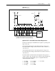
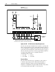
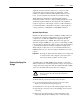
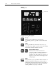
Figure 2.6 c
Option L6/L6E Wiring
Typical
AA
ENC
RET
ENC
12V
115V AC
Fuse
Common
Typical
12V
681
100
90.9
5V
JP4
19 20 21 22 23 24 25 26 27 28 29 30 31 32 33 34 35 36
0.15µf
0.33µf
0.22µf
49
499k
20k
100 100
User Supplied
115V AC
Contacts shown are general, refer to Figure 2.5 for
Input Mode selection and recommended contact types.
Fuse
TB3
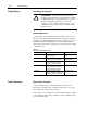
Option L6/L6E – 115V AC Interface Board Requirements
Circuits used with Option L6/L6E must be capable of operating with
high = true logic. In the low state, circuits must generate a voltage of
no more than 30V AC. Leakage current must be less than 10 mA into
a 6.5k ohm load. In the high state, circuits must generate a voltage of
90-115V AC ±10% and source a current of approximately 20 mA for
each input. The L6/L6E option is compatible with these
Allen-Bradley PLC modules:
• 1771-OW • 1771-OA
• 1771-OWN • 1771-OAD
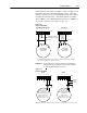
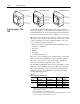
Encoder Wiring
Encoders must be line driver type, quadrature or pulse, 5V DC or
8-15V DC output, single-ended or differential and capable of
supplying a minimum of 10mA per channel. Maximum input
frequency is 125 kHz. Encoder inputs (TB3, terminals 31-36) cannot
be used if Pulse Train inputs (TB2-7, 8) are being used.