
Owner's manual

2–18 Installation/Wiring
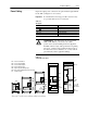
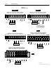
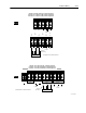
Figure 2.2
Terminal Block TB1
GRD GRDGRD GRD R
(L1)
S
(L2)
T
(L3)
DC
+
BRK
2
–
DC
–
COM
U
(T1)
V
(T2)
W
(T3)
AC Input Line
To Motor
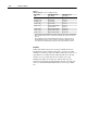
380-480V, 5.5-7.5 kW (7.5-10 HP) Terminal Designations
500-600V, 0.75-3.7 kW (1-5 HP) Terminal Designations
PE PE
R
(L1)
S
(L2)
T
(L3)
U
(T1)
V
(T2)
W
(T3)
DC
+
DC
–
AC Input Line
To Motor
To Motor
To Motor
200-240V, 5.5 kW (7.5 HP) Terminal Designations
380-480/500-600V, 5.5-11 kW (7.5-15 HP) Terminal Designations
Dynamic Brake
Dynamic Brake
Required
Input Fusing
1
To Motor
Required
Input Fusing
1
Required
Input Fusing
1
1
User supplied.
A4 Frame
B1 Frame
PE PE
R
(L1)
S
(L2)
T
(L3)
U
(T1)
V
(T2)
W
(T3)
DC
+
DC
–
Required
Input Fusing
AC Input Line
To Motor
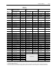
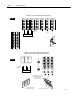
200-240V, 7.5-11 kW (10-15 HP) Terminal Designations
380-480V, 15-22 kW (20-30 HP) Terminal Designations
500-600V, 15 kW (20 HP) Terminal Designations
Dynamic Brake
To Motor
1
B2 Frame
1
Required Branch
Circuit Disconnect
1
Required Branch
Circuit Disconnect
1
Required Branch
Circuit Disconnect
R
(L1)
S
(L2)
T
(L3)
DC
+
DC
–
U
(T1)
V
(T2)
W
(T3)
AC Input Line
To Motor
200-240V, 0.37-3.7 kW (0.5-5 HP) Terminal Designations
380-480V, 0.37-3.7 kW (0.5-5 HP) Terminal Designations
Dynamic Brake
Option
DC Input Line
2
Terminal located separately on Series A Drives.
A1-A3 Frame
1
Required Branch
Circuit Disconnect
Important: A brake malfunction
will occur if the Dynamic Brake is
connected to "DC – COM"
PE
GRD
PE
GRD
DC
+
Dynamic Brake
Required
Input Fusing
1
DC
–
R
(L1)
S
(L2)
T
(L3)
W
(T3)
U
(T1)
V
(T2)
To Motor
AC Input Line
200-240V, 15-22 kW (20-30 HP) Terminal Designations
380-480V, 30-45 kW (40-60 HP) Terminal Designations
500-600V, 18.5-45 kW (25-60 HP) Terminal Designations
C Frame
1
Required Branch
Circuit Disconnect
To Motor