
Owner's manual


A
AC Supply Source, 2–3
Adapter Definitions, 2–38
Alarms, 6–8
Analog Invert, 5–15
Auto Restart, 5–22
B
Bypass Contactors, 2–6
C
Cable Termination, 2–34
Catalog Number Explanation, 1–2
CE Conformity, 2–8, C–1
Common Mode Cores, 2–34
Contacts, Fault, 6–1
Control Interface Option
Board Removal/Installation, 2–37
L4/L4E, 2–30
L5/L5E, 2–31
L6/L6E, 2–32
TB3 Description, 2–25
Control Status Mode, 3–5
Custom Volts/Hz, 5–51
D
DC Brake to Stop, 5–17
Derate Guidelines, A–5
Dimensions
Frame G Mounting Hardware, B–18
Heat Sink Through the Back, B–10,
B–11
IP 20 (NEMA Type 1)
Bottom Views, B–8
Front Views, B–2
IP 65/54 (NEMA Type 4/12),
Enclosure, B–7
TB1 – Frame G, B–17
TB1 – Frames D & E, B–16
Display Mode, 3–5
Distances Between Devices, 2–38
Distribution Systems
Unbalanced, 2–3
Ungrounded, 2–3
Drive Status Structure, A–13
Dwell, 5–21
E
EEProm Mode, 3–5
Electrostatic Discharge (ESD), 1–2
Encoder Wiring, 2–32
Engineering Unit, 5–6
ENUM, 5–6
F
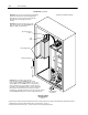
Fan Voltage, Selecting/Verifying, 2–35
Fault Buffer History, 5–29
Faults
Adptr Freq Err, 6–2
Auxiliary, 6–2
BGND 10ms Over, 6–2
Blwn Fuse Flt, 6–2
Diag C Lim Flt, 6–2
Drive –> HIM, 6–2
Drive Fault Reset, 6–2
EE Init Read, 6–2
EE Init Value, 6–2
EEprom Checksum, 6–2
EEprom Fault, 6–2
FGND 10ms Over, 6–2
Ground Fault, 6–3
Ground Warning, 6–3
Hertz Err Fault, 6–3
Hertz Sel Fault, 6–3
HIM –> Drive, 6–3
Loop Overrn Flt, 6–3
Max Retries Fault, 6–3
Motor Mode Flt, 6–3
Motor Stall Fault, 6–4
Neg Slope Fault, 6–4
Op Error Fault, 6–4
Open Pot Fault, 6–4
Overcurrent Flt, 6–4
Overload Fault, 6–4
Overtemp Fault, 6–4
Overvolt Fault, 6–4
P Jump Err Flt, 6–5
Phase U Fault, 6–4
Phase V Fault, 6–5
Phase W Fault, 6–5
Poles Calc Flt, 6–5
Power Loss Fault, 6–5
Power Mode Fault, 6–5
Power Overload, 6–5
Power Test Flt, 6–5
Precharge Fault, 6–5
Precharge Open, 6–5
Reprogram Fault, 6–6
ROM or RAM Fault, 6–6
Index