
Owner's manual

A–13Specifications and Supplemental Information
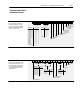
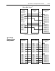
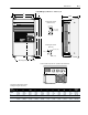
Drive Status Structure
This provides the drive status in-
formation that will be sent to the
logic controllers input image table
when the Communication Module
is set to control the drive.
Enabled
Running
Command Direction
Actual Direction
Accelerating
Decelerating
Faulted
At Speed
Bit 15 Bit 14 Bit 13 Bit 12 Bit 11 Bit 10 Bit 9 Bit 8 Bit 7 Bit 6 Bit 5 Bit 4 Bit 3 Bit 2 Bit 1 Bit 0
Alarm
0 = Reverse
1 = Forward
0 = Reverse
1 = Forward
Reference
ID
Local
Adapter ID
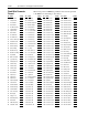
Reference 15 14 13 12
Freq Select 1 0 0 0 0
Preset Freq 1 0 0 0 1
Preset Freq 2 0 0 1 0
Preset Freq 3 0 0 1 1
Preset Freq 4 0 1 0 0
Preset Freq 5 0 1 0 1
Preset Freq 6 0 1 1 0
Preset Freq 7 0 1 1 1
Freq Select 2 1 0 0 0
Adapter 1 1 0 0 1
Adapter 2 1 0 1 0
Adapter 3 1 0 1 1
Adapter 4 1 1 0 0
Adapter 5 1 1 0 1
Adapter 6 1 1 1 0
Jog Frequency 1 1 1 1
Local 11 10 9
TB3 0 0 0
1001
2010
3011
4100
5101
6110
Unused 1 1 1
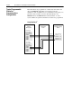
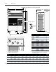
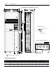
Logic Control Structure
This information provides the con-
trol logic information that is sent to
the drive through the logic control-
lers output image table when the
Communication Module is set to
control the drive.
Stop
Start
Jog
Clear Faults
MOP Increment
Bit 15 Bit 14 Bit 13 Bit 12 Bit 11 Bit 10 Bit 9 Bit 8 Bit 7 Bit 6 Bit 5 Bit 4 Bit 3 Bit 2 Bit 1 Bit 0
Local Lockout
Reference Select
Reference 14 13 12
No Command 0 0 0
Freq Select 1 0 0 1
Freq Select 2 0 1 0
Preset Freq 3 0 1 1
Preset Freq 4 1 0 0
Preset Freq 5 1 0 1
Preset Freq 6 1 1 0
Preset Freq 7 1 1 1
Accel TimeDecel Time Direction
Direction 5 4
No Command 0 0
Forward 0 1
Reverse 1 0
Hold Direction 1 1
Time 9/11 8/10
No Command 0 0
Time 1 0 1
Time 2 1 0
Hold Time 1 1
MOP Decrement
Communications Data
Information Format