
Owner's manual

5–26 Programming
This group of parameters contains the programming options for digital and analog drive
outputs. This group was named “Output Config” in firmware versions before 4.01.
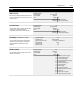
I/O Config
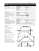
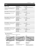
[Input Mode]
This parameter selects the functions of inputs 1-8 at
TB3 when an optional interface card is installed.
Refer to Input Mode Selection figure in Chapter 2.
This parameter cannot be changed while the drive is
running. Power to the drive must be cycled before
any changes will affect drive operation.
Parameter Number 21
Parameter Type Read and Write
Display Units / Drive Units Mode Number / Selection
Factory Default 1
Minimum Value 1
Maximum Value 24
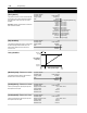
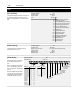
[CR1-4 Out Select]–Firmware 4.01 & later
This parameter sets the condition that changes the
state of the output contacts at TB2 terminals 10 & 11
(CR1), 11 & 12 (CR2), 13, 14, 15 (CR3) and 16, 17,
18 (CR4).
A change of state may mean energize or
de-energize the relay, since some relays may
energize on power-up and de-energize when the
selected condition occurs.
A red LED located on the Main Control Board
indicates the status of the CR3 contact. The LED will
illuminate when the contacts at terminals 13 & 14 of
TB2 are closed and terminals 14 & 15 are open.
Parameter Number 158, 174-176
Parameter Type Read and Write
Factory Default “At speed” CR1
“Running” CR2
“Fault” CR3
“Alarm” CR4
Units Display Drive
“Running” 2
Outputting frequency
“At Speed” 3 Output = command
“At Freq” 4 Requires value in [Dig Out Freq]
“At Current” 5 Requires value in [Dig Out Curr]
“At Torque” 6 Requires value in [Dig Out Torque]
“Current Lmt” 7 In overload
“Mtr Overload” 8 At present levels O.L. will occur
“Line Loss” 9 Line loss in progress
“Drive Power” 10 Full input volts present, bus charged
“Drive Ready” 11 All necessary commands present
“Forward Run” 12 Forward direction
“Reverse Run” 13 Reverse direction
“Braking” 14 DC brake mode (stopping or holding)
“Economize” 15 Auto economizer active
“Auto Reset” 16 Attempt to reset fault & restart drive
“Fault” 0 Any fault
“Alarm” 1 Any unmasked alarm
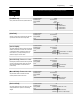
[Digital Out Sel] – Firmware below 4.01
This parameter sets the condition that closes the
output contact at TB2 terminals 10 & 11.
Parameter Number 158
Parameter Type Read and Write
Factory Default “At Speed”
Units Display Drive
“At Speed” 0
“At Frequency” 1
Requires value in [Dig Out Freq]
“At Current” 2 Requires value in [Dig Out Curr]
“At Torque” 3 Requires value in [Dig Out Torque]
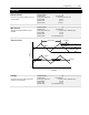
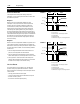
[Dig Out Freq]
This value sets the trip point for the output contact at
TB2 terminals 10 & 11 when [Digital Out Sel] is set
to “At Frequency”. The contact will be closed when
above this value.
Parameter Number 159
Parameter Type Read and Write
Display Units / Drive Units 0.01 Hertz / 32767 = Max Freq
Factory Default 0.00 Hz
Minimum Value 0.00 Hz
Maximum Value Programmed [Maximum Freq]
[Dig Out Current]
This value sets the trip point for the output contact at
TB2 terminals 10 & 11 when [Digital Out Sel] is set
to “At Current”. The contact will be closed when
above this value.
Parameter Number 160
Parameter Type Read and Write
Display Units / Drive Units 0% / 4096 = 100% of Drive Rated Amps
Factory Default 0 %
Minimum Value 0 %
Maximum Value 200 %