336 PLUS Adjustable Frequency AC Drive with 0.37-448 kW (0.5 - 600 HP) FRN 1.xx - 5.
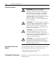
Important User Information Solid state equipment has operational characteristics differing from those of electromechanical equipment. “Safety Guidelines for the Application, Installation and Maintenance of Solid State Controls” (Publication SGI-1.1 available from your local Allen-Bradley Sales Office or online at http:// www.ab.com/manuals/gi) describes some important differences between solid state equipment and hard-wired electromechanical devices.
Summary of Changes The information below summarizes the changes to the 1336 PLUS User Manual since the last release. Description of New or Updated Information Incorporated 1336S–DU002A–EN–P and 1336 PLUS–5.3DU3 Document Updates. Notes added to mounting diagram. ! See Page(s) 5–54 & 2–36 2–1 ATTENTION: With the release of Firmware Version 4.01 & up, the resolution of several parameters has been enhanced to 0.1 units.
Notes
Table of Contents Information and Precautions Chapter 1 Installation/Wiring Chapter 2 Manual Objectives . . . . . . . . . . . . . . . . . . . . . . . . . . . . . . . . . . . . Software Compatibility . . . . . . . . . . . . . . . . . . . . . . . . . . . . . . . . . General Precautions . . . . . . . . . . . . . . . . . . . . . . . . . . . . . . . . . . Conventions Used in this Manual . . . . . . . . . . . . . . . . . . . . . . . . . Catalog Number Explanation . . . . . . . . . . . . . . . . . . . . . . .
ii Table of Contents Troubleshooting Chapter 6 Fault Descriptions . . . . . . . . . . . . . . . . . . . . . . . . . . . . . . . . . . . . Alarms . . . . . . . . . . . . . . . . . . . . . . . . . . . . . . . . . . . . . . . . . . . . Specifications and Supplemental Information Appendix A Specifications . . . . . . . . . . . . . . . . . . . . . . . . . . . . . . . . . . . . . . . User Supplied Enclosures . . . . . . . . . . . . . . . . . . . . . . . . . . . . . . Derating Guidelines . . . . . . . . . . .
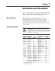
Chapter 1 Information and Precautions Chapter 1 provides information on the general intent of this manual, gives an overall description of the 1336 PLUS Adjustable Frequency AC Drive and provides a listing of key drive features. Manual Objectives This publication provides planning, installation, wiring and diagnostic information for the 1336 PLUS Drive. To assure successful installation and operation, the material presented must be thoroughly read and understood before proceeding.
1–2 Information and Precautions General Precautions ! ! ! ! Conventions Used in this Manual ATTENTION: This drive contains ESD (Electrostatic Discharge) sensitive parts and assemblies. Static control precautions are required when installing, testing, servicing or repairing this assembly. Component damage may result if ESD control procedures are not followed. If you are not familiar with static control procedures, reference A-B publication 8000-4.5.
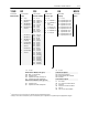
Information and Precautions 1–3 1336S BR F30 AA EN MODS First Position Second Position Third Position Fourth Position Fifth Position Sixth Position Bulletin Number Voltage Nominal HP Rating Enclosure Type Language Options Letter Voltages Code kW (HP) Code Type Code AQ 200-240V AC or 310V DC F05 F07 F10 F15 F20 F30 F50 F75 F100 0.37 (0.5) 0.56 (0.75) 0.75 (1) 1.2 (1.5) 1.5 (2) 2.2 (3) 3.7 (5) 5.5 (7.5) 7.5 (10) AA IP 20 (NEMA 1) AE IP 20 (NEMA 1)/ EMC 0.37-45 kW (0.
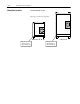
1–4 Information and Precautions Nameplate Location 1336 PLUS Nameplate Location 1 Refer to page 1-1 for frame reference classifications.
Chapter 2 Installation/Wiring Chapter 2 provides the information you need to properly mount and wire the 1336 PLUS Drive. Since most start-up difficulties are the result of incorrect wiring, every precaution must be taken to assure that the wiring is done as instructed. All items must be read and understood before the actual installation begins. ATTENTION: The following information is merely a guide for proper installation.
2–2 Installation/Wiring Installation Guidelines GND AC Supply Source Page 2–3 CAT. NO. FREQUENCY POWER RATING PRIMARY VOLTAGE SECONDARY VOLTAGE INSULATION CLASS NO. OF PHASES VENDOR PART NO.
Installation/Wiring AC Supply Source 2–3 1336 PLUS drives are suitable for use on a circuit capable of delivering up to a maximum of 200,000 rms symmetrical amperes, 600 volts maximum when used with the AC input line fuses specified in Table 2.A. ATTENTION: To guard against personal injury and/or equipment damage caused by improper fusing, use only the recommended line fuses specified in Table 2.A.
2–4 Installation/Wiring Input Power Conditioning In general, the 1336 PLUS is suitable for direct connection to an AC line of the correct voltage. Certain conditions can exist, however, that prompt consideration of a line reactor or isolation transformer ahead of the drive. The basic rules to aid in determining whether a line reactor or isolation transformer should be considered are as follows: 1.
Installation/Wiring 2–5 Input Fusing ! ATTENTION: The 1336 PLUS does not provide input power short circuit fusing. Specifications for the recommended fuse size and type to provide drive input power protection against short circuits are provided. Branch circuit breakers or disconnect switches cannot provide this level of protection for drive components. Table 2.
2–6 Installation/Wiring Input Devices Starting and Stopping the Motor ! ATTENTION: The drive start/stop control circuitry includes solid-state components. If hazards due to accidental contact with moving machinery or unintentional flow of liquid, gas or solids exist, an additional hardwired stop circuit may be required to remove AC line power to the drive. When AC power is removed, there will be a loss of inherent regenerative braking effect & the motor will coast to a stop.
Installation/Wiring Electrical Interference – EMI/RFI 2–7 Immunity The immunity of 1336 PLUS drives to externally generated interference is good. Usually, no special precautions are required beyond the installation practices provided in this publication. It is recommended that the coils of DC energized contactors associated with drives be suppressed with a diode or similar device, since they can generate severe electrical transients.
2–8 Installation/Wiring RFI Filtering 1336 PLUS drives can be installed with an RFI filter, which controls radio-frequency conducted emissions into the main supply lines and ground wiring. If the cabling and installation recommendation precautions described in this manual are adhered to, it is unlikely that interference problems will occur when the drive is used with conventional industrial electronic circuits and systems.
Installation/Wiring 2–9 Encoder & Communications Cabling If encoder connections or communications cables are used, the wiring must be separated from power cabling. This can be accomplished with carefully routed, shielded cable (ground cable shield at the drive end only) or a separate steel conduit (grounded at both ends). Belden 9730, 8777 (or equivalent) is recommended for encoder cable runs less than 30 meters (100 feet).
2–10 Installation/Wiring General Grounding Common Mode Core* U (T1) Conduit/4-Wire Cable R (L1) ESC S (L2) Shield* V (T2) SEL JOG W (T3) PE/Gnd. T (L3) Shield Motor Frame PE Motor Terminator* RIO/DH+ or Analog Common Mode Core* Nearest Building Structure Steel To Computer/Position Controller (for TE shield ground, see "Control Connections") PE Ground per Local Codes * Options that can be installed as needed. See pages 2–34 and 2–35.
Installation/Wiring Power Cabling 2–11 Input and output power connections are performed through terminal block, TB1 (see Figure 2.1 for location). Important: For maintenance and setup procedures, the drive may be operated without a motor connected. Table 2.
2–12 Installation/Wiring Table 2.C TB1 Specifications – Use 75° C Copper wire Only Drive Frame Size Max./Min. Wire Size 1 mm 2 (AWG) Maximum Torque N-m (lb.-in.) A1-A4 (page 2–18) B1 (page 2–18) 5.3/0.8 (10/18) 8.4/0.8 (8/18) 1.81 (16) 1.81 (16) B2 (page 2–18) C (page 2–18) 13.3/0.5 (6/20) 26.7/0.8 (3/18) 1.70 (15) 5.65 (50) D (page 2–19) 3 127.0/2.1 (250 MCM/14) 67.4/2.1 (00/14) 2 6.00 (52) 6.00 (52) E (page 2–19) 3 F (page 2–20) 3 253.0/2.1 (500 MCM/14) 303.6/2.1 (600 MCM/14) 10.
Installation/Wiring 2–13 Table 2.D Lug Selection Drive Catalog Number 1 AC Input R, S, T Output U, V, W and PE Cable (per Phase) T&B Part No.3 1336S–A040 1336S–A050 1336S–A060 1336S–A075 Qty. (1) (1) (1) (2) mm 2 (AWG) 53.5 (1/0) 85.0 (3/0) 107.2 (4/0) 53.5 (1/0) 1336S–A100 (2) 85.0 (3/0) 1336S–A125 (2) 107.2 (4/0) 1336S–B060 1336S–B075 1336S–B100 1336S–B125 1336S–BX150 1336S–B150 (1) (1) (1) (1) (1) (2) 42.4 (1) 53.5 (1/0) 85.0 (3/0) 107.2 (4/0) 107.2 (4/0) 53.5 (1/0) 1336S–B200 (2) 85.
2–14 Installation/Wiring Motor Cables A variety of cable types are acceptable for drive installations. For many installations, unshielded cable is adequate, provided it can be separated from sensitive circuits. As an approximate guide, allow a spacing of 0.3 meters (1 foot) for every 10 meters (32.8 feet) of length. In all cases, long parallel runs must be avoided. Do not use cable with an insulation thickness less than or equal to 15 mils.
Installation/Wiring 2–15 Conduit If metal conduit is preferred for cable distribution, the following guidelines must be followed. • Drives are normally mounted in cabinets and ground connections are made at a common ground point in the cabinet. Normal installation of conduit provides grounded connections to both the motor frame ground (junction box) and drive cabinet ground. These ground connections help minimize interference.
2–16 Installation/Wiring Table 2.E Maximum Motor Cable Length Restrictions in meters (feet) – 380V-480V Drives 1 No External Devices Motor A B 1329 1329R/L Drive Frame Drive kW (HP) Motor kW (HP) Any Cable Any Cable Any Cable Any Cable 7 A1 0.37 (0.5) 0.37 (0.5) 0.75 (1) 0.75 (1) 12.2 (40) 12.2 (40) 12.2 (40) 12.2 (40) 12.2 (40) 12.2 (40) 7.6 (25) 7.6 (25) 7.6 (25) 7.6 (25) 7.6 (25) 7.6 (25) 7.6 (25) 7.6 (25) 7.6 (25) 7.6 (25) 7.6 (25) 7.6 (25) 7.6 (25) 7.6 (25) 7.6 (25) 7.6 (25) 12.
Installation/Wiring 2–17 Table 2.F Maximum Motor Cable Length Restrictions in meters (feet) – 500V-600V Drives 4 No External Devices Motor Drive Drive kW Frame (HP) A4 0.75 (1) 1.5 (2) 2.2 (3) 3.7 (5) A B Any Cable Any Cable 1600V or 1329R/L 6 Any Cable 182.9 (600) NR 182.9 (600) NR 182.9 (600) NR NR NR 182.9 (600) 1.2 (1.5) NR NR 0.75 (1) NR 0.37 (0.5) w/ 1204-TFA1 Terminator Motor A B Any Cable Any Cable 1600V or 1329R/L Any Cable 335.3 (1100) NR 61.0 (200) 182.
2–18 Installation/Wiring Figure 2.2 Terminal Block TB1 A1-A3 Frame A4 Frame 200-240V, 0.37-3.7 kW (0.5-5 HP) Terminal Designations 380-480V, 0.37-3.7 kW (0.5-5 HP) Terminal Designations 380-480V, 5.5-7.5 kW (7.5-10 HP) Terminal Designations 500-600V, 0.75-3.
Installation/Wiring 2–19 200-240V, 30-45 kW (40-60 HP) Terminal Designations 380-480V, 45-112 kW (60-150 HP) Terminal Designations 500-600V, 56-112 kW (75-150 HP) Terminal Designations D Frame DC + Brake DC – Brake PE PE TE To Motor S (L2) R (L1) U (T1) T (L3) V (T2) W (T3) To Motor 1 1 Required Branch Circuit Disconnect Required Input Fusing See Appendix B for detailed Dimensions.
2–20 Installation/Wiring 380-480V, 187-336 kW (250-450 HP) Terminal Designations F Frame R-L1 PE T-L3 S-L2 U-M1 W-M3 V-M2 Input Fusing (Supplied) To Motor 1 Required Branch Circuit Disconnect AC Input Line typical terminal DC – Brake DC + Brake 380-480V, 224-448 kW (300-600 HP) Terminal Designations 500-600V, 187-448 kW (250-600 HP) Terminal Designations DC + Brake G Frame S (L2) T (L3) R (L1) DC – Brake Required 1 Input Fusing U (M1) 1 Required Branch Circuit Disconnect V (M2) W (
Installation/Wiring Control and Signal Wiring 2–21 Terminal Block TB2 TB2 is located at the bottom of the Main Control Board. 0.37-7.5 kW (0.5-10 HP) A Frame drives have 18 positions. Remaining frame sizes from 5.5 kW (7.5 HP) and up have 22 positions. The maximum and minimum wire size accepted by TB2 is 2.1 and 0.30 mm2 (14 and 22 AWG). Maximum torque for all terminals is 1.36 N-m (12 lb.-in.). Use Copper wire only. See Figures 2.1 and 2.3.
2–22 Installation/Wiring Figure 2.3 TB2 Connections 10 Bit A/D 10 Bit A/D 10 Bit A/D Typical 150 47.5k 1µf 52.3k 1µf 75k TE TE 2 1.4k 100 3 4 5 – 6 + 7 + 8 – CR4 CR4 + 11 12 13 14 15 16 17 18 Only Present on B Frame & Up Drives A1 A2 + Contacts Shown in Unpowered State (or Powered State with Fault/Alarm Present) 4-20mA 10k Ohm 10 9 0-10V to TE CR3 CR3 215 CR1 CR2 100 1 100 1µf Logic Common Only Present on B Frame & Up Drives 12 Bit D/A 215 3.
Installation/Wiring 2–23 Pulse Input ATTENTION: If reverse polarity or voltage levels are maintained above +12V DC, signals may be degraded and component damage may result. ! The pulse input signal must be an externally powered square-wave pulse at a 5V TTL logic level. Circuits in the high state must generate a voltage between 4.0 and 5.5V DC at 16 mA. Circuits in the low state must generate a voltage between 0.0 and 0.4V DC. Maximum input frequency is 125kHz.
2–24 Installation/Wiring Available Inputs A variety of combinations made up of the following inputs are available. Input 1st/2nd Accel/Decel Auxiliary Digital Pot Up/Down Enable Integrator Reset (NOT) Local Control PI Output Reverse Reverse or Forward Run Forward/Reverse Speed Select 1, 2, 3 Start Stop Type Stop/Fault Reset Description These inputs allow selection of the accel or decel time used by the drive.
Installation/Wiring 2–25 The available combinations are shown in Figure 2.5. Programming the [Input Mode] parameter to one of the Input Mode numbers listed, will select that combination of input functions. Important: If a Control Interface Option is not installed, the [Input Mode] parameter must be set to 1 (default) and jumpers must be installed as shown in Figure 2.7. If the drive was shipped from the factory without the option, these jumpers will have been installed.
2–26 Installation/Wiring Speed Select/Frequency Reference The drive speed command can be obtained from a number of different sources. The source is determined by drive programming and the condition of the Speed Select Inputs on TB3 (or reference select bits of command word if PLC controlled – see Appendix A). The default source for a command reference (all speed select inputs open) is the selection programmed in [Freq Select 1].
Installation/Wiring 2–27 Example 2 Input Mode 7 – Application is to follow a local HIM unless a preset speed is selected. The drive is programmed as follows: – – – – – [Freq Select 1] = Adapter 1 [Freq Select 2] = Preset Freq 1 [Preset Freq 1] = 10 Hz. [Preset Freq 2] = 20 Hz. [Preset Freq 3] = 30 Hz. Contact operation for the speed select switch is described in the table below. Since Input Mode 7 does not offer a Speed Select 3 input, [Preset Freq 4-7] are not available.
2–28 Installation/Wiring Figure 2.5 Input Mode Selection & Typical TB3 Connections Momentary Maintained See Figure 2.6 for Wiring Information [Input Mode] 1 Factory Default 19 Status 20 Stop/Fault Reset 3 21 Common 22 Status 23 Status 24 Status 25 Common 26 Status 27 Status 28 Status 29 Common 30 Enable 3 Note: If this mode is selected, the status of all inputs can be read at the [Input Status] parameter. However, only “Stop/Fault Reset” and “Enable” will have control function.
Installation/Wiring 2–29 19 Start 20 Stop/Fault Reset 3 21 Common 22 23 24 Auxiliary 3 25 Common 7 27 9 Mode 10 Speed Select 1 1 29 Common 30 Enable 3 19 5 23 8 1st Accel Reverse4 Reverse4 Forward4 Forward4 Digital Forward4 Pot Dn 2nd Accel Forward4 Forward4 Speed Speed Digital Select 31 Select 31 Pot Up Speed Speed Speed Digital Select 21 Select 21 Select 21 Pot Dn 28 11 Reverse4 Reverse4 Digital Reverse4 Pot Up Jog 7 26 8 1st Integrator Integrator Decel Reset 6 Reset 6
2–30 Installation/Wiring Figure 2.6 a Option L4/L4E Wiring Typical 0.1µf 0.1µf 10.7k 10.7k 100 Typical 681 Isolated +5V 5V JP4 470 0.1µf 12V 470 90.9 Isolated Ground A IGND 19 20 21 22 23 24 25 26 27 28 29 30 31 32 A 33 34 ENC 12V 35 ENC RET 36 TB3 Contacts shown are general, refer to Figure 2.5 for Input Mode selection and recommended contact types.
Installation/Wiring 2–31 Figure 2.6 b Option L5/L5E Wiring 510 510 100 Typical 20k Typical 0.22µf 681 5V JP4 510 12V 1k 90.9 A 19 20 21 22 23 24 25 26 27 28 29 30 31 32 A 33 34 ENC 12V 35 ENC RET 36 TB3 Common User Supplied 24V AC/DC +24V Contacts shown are general, refer to Figure 2.5 for Input Mode selection and recommended contact types.
2–32 Installation/Wiring Figure 2.6 c Option L6/L6E Wiring 100 100 20k Typical 0.15µf 100 Typical 0.22µf 0.33µf 681 5V 499k JP4 12V 49 90.9 A 19 20 21 22 23 24 25 26 27 28 29 30 31 32 A 33 34 ENC 12V 35 ENC RET 36 TB3 Common Fuse 115V AC Fuse User Supplied 115V AC Contacts shown are general, refer to Figure 2.5 for Input Mode selection and recommended contact types.
Installation/Wiring 2–33 The interface board is jumper selectable to accept a 5V TTL or 12V DC square-wave with a minimum high state voltage of 3.0V DC (TTL) or 7.0V DC (12 volt encoder). Maximum low state voltage is 0.4V DC. Recommended wire – shielded, 0.750 mm2 (18 AWG), 305 m (1000 ft.) or less. Maximum input frequency is 125kHz. See Encoder & Communications Cabling on page 2–9. Figure 2.
2–34 Installation/Wiring Output Devices Drive Output Disconnection ! ATTENTION: Any disconnecting means wired to the drive output terminals U, V and W must be capable of disabling the drive if opened during drive operation. If opened during drive operation, the drive will continue to produce output voltage between U, V, W. An auxiliary contact must be used to simultaneously disable the drive.
Installation/Wiring 2–35 Applications with non-inverter duty motors or any motor with exceptionally long leads may require an output filter or cable terminator. A filter or terminator will help limit reflection to the motor, to levels which are less than the motor insulation rating. Table 2.E lists the maximum recommended cable length for unterminated cables, since the voltage doubling phenomenon occurs at different lengths for different drive ratings.
2–36 Installation/Wiring 380-480V AC Input Voltage 200-240V AC Input Voltage 200 Volt Tap (use for 200-220V) 500-600V AC Input Voltage 500 Volt Tap (use for 500V) 380 Volt Tap (use for 380-400V) 415 Volt Tap (use for 415V) Auxiliary Inputs – TB4, TB6 575 Volt Tap (use for 575-600V) 460 Volt Tap (use for 460-480V) 240 Volt Tap (use for 230-240V) Terminal blocks TB4 and TB6 (B Frame drives & up) allow the drive power supplies to be operated from an external voltage source.
Installation/Wiring Auxiliary Output – TB9 2–37 The 480 or 600V (depending on input voltage to drive) output terminal block (TB9) is only available on F Frame Drives. This terminal block provides a three-phase, high voltage connection from the load side of the AC input line fuses. Normally this connection is used to power an external control transformer (user supplied) or other auxiliary circuit. Refer to Figure 2.1 for location.
2–38 Installation/Wiring Adapter Definitions Serial communication devices such as the Human Interface Module that are connected to the drive are identified by SCANport serial communications as Adapters. Depending on the drive and options ordered, a number of different adapters are available as shown in Figure 2.8. Figure 2.9 shows the maximum distance allowed between devices. Figure 2.
Chapter 3 Human Interface Module Chapter 3 describes the various controls and indicators found on the optional Human Interface Module (HIM). The material presented in this chapter must be understood to perform the start-up procedure in Chapter 4. HIM Description When the drive mounted HIM is supplied, it will be connected as Adapter 1 (see Adapter Definitions in Chapter 2) and visible from the front of the drive. The HIM can be divided into two sections; Display Panel and Control Panel.
3–2 Human Interface Module Figure 3.2 HIM Display Panel LCD Display Display Panel Key Descriptions Escape When pressed, the ESCape key will cause the programming system to go back one level in the menu tree. Select Pressing the SELect key alternately causes the top or bottom line of the display to become active. The flashing first character indicates which line is active. Increment/Decrement These keys are used to increment and decrement a value or scroll through different groups or parameters.
Human Interface Module 3–3 Figure 3.3 HIM Control Panel Digital Speed Control and Indicator (also available with Analog Speed Pot.) Control Panel Key Descriptions Start The Start key will initiate drive operation if no other control devices are sending a Stop command. This key can be disabled by the [Logic Mask] or [Start Mask]. Stop If the drive is running, pressing the Stop key will cause the drive to stop, using the selected stop mode.
3–4 Human Interface Module Control Panel Key Descriptions (Continued) Change Direction Pressing this key will cause the drive to ramp down to zero Hertz and then ramp up to set speed in the opposite direction. The appropriate Direction Indicator will illuminate to indicate the direction of motor rotation. Refer to [Logic Mask] and [Direction Mask]. Direction LEDs (Indicators) The appropriate LED will illuminate continuously to indicate the commanded direction of rotation.
Human Interface Module 3–5 Figure 3.4 Status Display From this display, pressing any one of the 5 Display Panel keys will cause “Choose Mode” to be displayed. Pressing the Increment or Decrement keys will allow different modes to be selected as described below and shown in Figure 3.5. Refer to the pages that follow for operation examples. Display When selected, the Display mode allows any of the parameters to be viewed. However, parameter modifications are not allowed.
3–6 Human Interface Module Figure 3.
Human Interface Module Program and Display Modes 1. The Display and Program modes allow access to the parameters for viewing or programming. A. From the Status Display, press Enter (or any key). “Choose Mode” will be shown. or B. Press the Increment (or Decrement) key to show “Program” (or “Display”). Choose Mode Display Choose Mode Program C. Press Enter. or D. Press the Increment (or Decrement) key until the desired group is displayed. Choose Group Metering E. Press Enter.
3–8 Human Interface Module Process Mode or 1. When selected, the Process mode will show a custom display consisting of information programmed with the Process Display group of parameters. A. Follow steps A-C on the preceding page to access the Program mode. Choose Mode Program B. Press the Increment/Decrement key until “Process Display” is shown. Press Enter. Choose Group Process Display C.
Human Interface Module EEProm Mode The EEProm mode is used to restore all settings to factory default values or upload/ download parameters between the HIM and drive (Series B HIM, Only). Reset Defaults 1. To restore factory defaults: A. From the Status Display, press Enter (or any key). “Choose Mode” will be displayed. B. Press the Increment (or Decrement) key until “EEProm” is displayed. If EEProm is not in the menu, programming is password protected. Refer to Password Mode later in this section.
3–10 Human Interface Module Drive –> HIM (continued) C. Press Enter. An informational display will be shown, indicating the drive type and firmware version. D. Press Enter to start the upload. The parameter number currently being uploaded will be displayed on line 1 of the HIM. Line 2 will indicate total progress. Press ESC to stop the upload. HIM –> Drive E. “COMPLETE” displayed on line 2 will indicate a successful upload. Press Enter. If “ERROR” is displayed, see Chapter 6. 3.
Human Interface Module Search Mode 1. The Search Mode is only available with a Series A (version 3.0) or Series B HIM. This mode allows you to search through the parameter list and display all parameters that are not at the factory default values. A. From the Status Display, press Enter (or any key). “Choose Mode” will be shown. B. Press the Increment (or Decrement) key until “Search” is displayed. or Choose Mode Display Choose Mode Search C. Press Enter.
3–12 Human Interface Module Control Status Mode (continued) 2. This menu provides a means to view the fault queue and clear it when desired. Fault Queue/Clear Faults A. From the Control Status menu, press the Increment (or Decrement) key until “Fault Queue” is displayed. or Control Status Fault Queue B. Press Enter. C. Press the Increment (or Decrement) key until “View Faults” is displayed. or D. Press Enter. The fault queue will be displayed.
Human Interface Module Password Mode or 1. The factory default password is 0 (which disables password protection). To change the password and enable password protection, perform the following steps. A. From the Status Display, press Enter (or any key). “Choose Mode” will be shown. Choose Mode Display B. Press the Increment (or Decrement) key until “Password” is displayed. Choose Mode Password C. Press Enter. or or or and D. Press the Increment (or Decrement) key until “Modify” is displayed.
3–14 Human Interface Module Password Mode (continued) Login to the Drive or 2. The Program/EEProm modes and the Control Logic/Clear Queue menus are now password protected and will not appear in the menu. To access these modes, perform the following steps. A. Press the Increment (or Decrement) key until “Password” is displayed. B. Press Enter. “Login” will be displayed. C. Press Enter, “Enter Password” will be displayed. or Logout from the Drive or Password Login Enter Password < 0> D.
Human Interface Module Module Removal 3–15 For handheld operation, the module can be removed and located up to 10 meters (33 feet) from the drive. Refer to Adapter Definitions in Chapter 2 for details. ! Important: ATTENTION: Some voltages present behind the drive front cover are at incoming line potential. To avoid an electric shock hazard, use extreme caution when removing/replacing the HIM.
3–16 Human Interface Module End of Chapter
Chapter 4 StartĆUp This chapter describes how you start-up the 1336 PLUS Drive. Included are typical adjustments and checks to assure proper operation. The information contained in previous chapters of this manual must be read and understood before proceeding. Important: The 1336 PLUS is designed so that start-up is simple and efficient. The programmable parameters are grouped logically so that most start-ups can be accomplished by adjusting parameters in only one group.
4–2 Start-Up Initial Operation – Motor Disconnected 1. Verify that AC line power at the disconnect device is within the rated value of the drive. If a Control Interface option (L4, L5, L6, L4E, L5E, L6E) is installed, verify that the control power to this board matches the board rating. 2. Remove and lock-out all incoming power to the drive including incoming AC power to terminals R, S and T (L1, L2 and L3) plus any separate control power for remote interface devices.
Start-Up Apply Power 7. Apply AC power and control voltages to the drive. The LCD Display should light and display a drive status of “Stopped” and an output frequency of “+0.00 Hz.” Stopped +0.00 Hz If the drive detects a fault, a brief statement relating to the fault will be shown on the display. Record this information, remove all power and correct the fault source before proceeding. Refer to Chapter 6 for fault descriptions. 8.
4–4 Start-Up Program Input Mode 9. If a Control Interface option is installed, it is important that the Input Mode recorded in Chapter 2 be programmed into the drive. Since the control inputs to this option are programmable, incorrect operation can occur if an improper mode is selected. The factory default input mode disables all inputs except Stop and Enable. Verify your control scheme against the information provided in Chapter 2 and program the [Input Mode] parameter as follows: A.
Start-Up 10. Set [Maximum Freq] and [Maximum Voltage] parameters to correct values (typically line voltage/frequency). Set [Base Voltage] and [Base Frequency] parameters to the motor nameplate values. or or A. From the Status Display, press the Enter key (or any key). “Choose Mode” will be displayed. Choose Mode EEProm B. Press the Increment (or Decrement) key until “Program” is displayed. Choose Mode Program C. Press Enter. Metering D. Press the Increment key until “Setup” is displayed.
4–6 Start-Up 12. Setting Frequency Command. A. From the Status Display, press the Enter key (or any key). “Choose Mode” will be displayed. Choose Mode Program B. Press the Increment key until “Display” is shown. Choose Mode Display C. Press Enter. Setup D. Press the Decrement key until “Metering” is displayed. E. Press Enter. F. Press the Increment key until “Freq Command” is displayed. or Output Voltage 0 Vlts Freq Command +0.00 Hz G.
Start-Up 14. Checking Direction. A. Initiate a Reverse command. Important: With [Direction Mask] set to the default value, the reverse command must be issued from the HIM or other adapter. If the reverse command is to be issued from TB3, [Direction Mask] must first be programmed to allow direction control from TB3. The drive will ramp to zero speed, then ramp to [Maximum Freq] in the opposite direction.
4–8 Start-Up 16. Jog Control & Stop Mode Check. Press & Hold Jog Key Release Jog Key A. With the drive reset, but not running, press and hold the Jog key on the Control Panel. The motor should accelerate to the frequency programmed by the [Jog Frequency] parameter and remain there until the Jog key is released. When released, the drive should execute a stop function using the programmed stop mode. Verify that the correct stop mode was initiated. At Speed –10.00 Hz Stopped –0.00 Hz 17.
Start-Up ATTENTION: To avoid a hazard of electric shock, verify that the voltage on the bus capacitors has discharged. Measure the DC bus voltage at the + & – terminals of TB1. The voltage must be zero. ! Reconnect Motor B. Reconnect motor leads & replace cover. 19. Check for Correct Motor Rotation. ATTENTION: In the following steps, rotation of the motor in an undesired direction can occur.
4–10 Start-Up 20. Low Speed Operation. (Speed range greater than 20:1) If Volts/Hertz operation was selected in step 11, proceed to step 25. Slip @ F.L.A. Adjustment. To increase the steady state torque performance of the motor at low speeds, the default Speed Control method is Slip Compensation. The factory default value for [Slip @ F.L.A.] is “1.0 Hz.” Optimum motor performance depends on accurate setting of [Slip @ F.L.A.]. Estimate your motor slip value using the following: Motor Sync.
Start-Up Speed Control Selection 4–11 No Control Slip Comp. Speed Droop Phase Lock Loop * Encoder Feedback [Speed Control] Parameter 77 Droop + Regulator + Speed Adder ∑ Frequency Command + Speed Reference see page 2–26 P Jump Process PI * Firmware versions below 4.01 only. Program NP Data 21. Tuning Sensorless Vector operation. Firmware Version 4.01 & Up Only To further improve drive performance in Sensorless Vector mode, the actual motor nameplate data can be entered directly.
4–12 Start-Up or C. Press the Increment/Decrement keys until “Flux Current” is displayed. Start the drive and record this value. Stop the drive. Flux Current 1 Amp Flux Current = or D. Press the Increment/Decrement keys to display “Freq Command.” Adjust the speed source for the drive to zero Hz. Freq Command 0 Hz or E. Press the Increment (or Decrement) key to display “Output Voltage.” Start the drive and record the value. Output Voltage 0 Vlts F. Stop the drive. Output Voltage at 0 Hz = G.
Start-Up Set Power-Up Display or Set Electronic Overload 25. With HIM software versions 2.02 & up, the power-up display (Status, Process or Password) can be programmed to appear when drive power is applied. Simply access the desired display and simultaneously press the Increment and Decrement keys. 26. Electronic overload protection is factory set to drive maximum. A. To properly set the electronic overload protection, program [Overload Amps] (Setup group) to the actual nameplate F.L.A. B.
4–14 Start-Up End of Chapter
Chapter 5 Programming Chapter 5 describes parameter information for the 1336 PLUS. Parameters are divided into 14 groups for ease of programming and operator access. Grouping replaces a sequentially numbered parameter list with functional parameter groups that increases operator efficiency and helps to reduce programming time. For most applications, this means simplicity at startup with minimum drive tuning.
5–2 Programming OPERATOR LEVEL Power-Up Mode & Status Display ESC or SEL or or or "Choose Mode" MODE LEVEL Display (Read Only) Process Program (Read and Write) Parameter Groups Process Display Parameter Groups GROUP LEVEL Wraps to Linear List Metering Setup Advanced Setup Frequency Set Feature Select I/O Config Faults Diagnostics page 5-7 page 5-10 page 5-14 page 5-19 page 5-21 page 5-26 page 5-29 page 5-34 Minimum Freq Maximum Freq PWM Frequency Analog Trim En 4-20mA Loss
Programming 5–3 FIRMWARE VERSIONS 4.01 & UP EEPROM Reset Defaults Drive -> HIM 1 HIM -> Drive 1 Recall Values 2 Save Values 2 Series A (Version 3.0) and Series B HIM Only Series A (Version 3.0) and Series B HIM Only Search (Read Only) Control Status Password Control Logic Fault Queue Login, Logout, Modify 1 Series B HIM Only.
5–4 Programming OPERATOR LEVEL Power-Up Mode & Status Display ESC or SEL or or or "Choose Mode" MODE LEVEL Display (Read Only) Process Program (Read and Write) Parameter Groups Process Display Parameter Groups GROUP LEVEL Wraps to Linear List Metering Setup Advanced Setup Frequency Set Feature Select Output Config Faults Diagnostics page 5-7 page 5-10 page 5-14 page 5-19 page 5-21 page 5-26 page 5-29 page 5-34 Input Mode Freq Select 1 Accel Time 1 Decel Time 1 Base Frequenc
Programming 5–5 FIRMWARE VERSIONS 1.05 – 3.01 EEPROM Reset Defaults Drive -> HIM 1 HIM -> Drive 1 Recall Values 2 Save Values 2 Series A (Version 3.0) and Series B HIM Only Series A (Version 3.0) and Series B HIM Only Search (Read Only) Control Status Password Control Logic Fault Queue Login, Logout, Modify 1 Series B HIM Only. 2 Reserved for Future Use Wraps to Metering Ratings 2.01 Masks Owners Adapter I/O Process Display Encoder Feedback Process PI 3.
5–6 Programming Chapter Conventions Parameter descriptions adhere to the following conventions. 1. All parameters required for any given drive function will be contained within a group, eliminating the need to change groups to complete a function. 2. All parameters are documented as either having ENUMS or Engineering Units. ENUMS [Parameter Name] Parameter description.
Programming Metering [Output Current] This parameter displays the output current present at TB1, terminals T1, T2 & T3 (U, V & W). [Output Voltage] This parameter displays the output voltage present at TB1, terminals T1, T2 & T3 (U, V & W). [Output Power] This parameter displays the output power present at TB1, terminals T1, T2 & T3 (U, V & W). [DC Bus Voltage] This parameter displays the DC bus voltage level.
5–8 Programming Metering [4-20 mA Hertz] This parameter displays the frequency command present at analog current input terminals 4 & 6 of TB2. This value is displayed whether or not this is the active frequency command. [0-10 Volt Hertz] This parameter displays the frequency command present at analog voltage input terminals 4 & 5 of TB2. This value is displayed whether or not this is the active frequency command.
Programming 5–9 Metering [Power OL Count]– Firmware 4.01 & later Displays the percentage of accumulated I2t for the drive thermal overload protection. Running continuously above 115% of drive rated amps will accumulate a value of 100% and generate an Overtemp Fault (F08). [Motor OL Count]– Firmware 4.01 & later This parameter displays the percentage of accumulated I2t for the motor overload protection. Running continuously at programmed [Overload Amps] will accumulate approximately 70%.
5–10 Programming Setup [Input Mode] This parameter selects the functions of inputs 1-8 at TB3 when an optional interface card is installed. Refer to Input Mode Selection figure in Chapter 2. This parameter cannot be changed while the drive is running. Power to the drive must be cycled before any changes will affect drive operation.
Programming 5–11 Setup Constant Speed D e ce Speed ion lerat A c ce lerat ion Accel/Decel Time 0 Accel Time Time Decel Time 0 [Minimum Freq] This parameter sets the lowest frequency the drive will output. [Maximum Freq] This parameter sets the highest frequency the drive will output. This parameter cannot be changed while the drive is running. [Stop Select 1] This parameter selects the stopping mode when the drive receives a valid stop command unless [Stop Select 2] is selected.
5–12 Programming Setup Parameter Number Parameter Type Factory Default Units [Current Lmt Sel]– Firmware 4.01 & later Selects the source of the [Current Limit] setting for the drive. When an external input is selected (0-10V or 4-20 mA), the minimum signal (0V or 4 mA) sets 20% current limit and the maximum signal (10V or 20mA) sets the value programmed in [Current Limit]. 232 Read and Write “Current Lmt” Display Drive “Current Lmt” 0 Use [Current Limit], param. 36.
Programming 5–13 Setup [Overload Amps] This value should be set to the motor nameplate Full Load Amps (FLA) for 1.15 SF motors. For 1.0 SF motors the value should be set to 0.9 x nameplate FLA. [VT Scaling] This parameter scales the drive for VT ampere ratings. Parameter Number 38 Parameter Type Read and Write Display Units / Drive Units 0.
5–14 Programming Advanced Setup [Minimum Freq] This parameter sets the lowest frequency the drive will output. [Maximum Freq] This parameter sets the highest frequency the drive will output. This parameter cannot be changed while the drive is running. This group contains parameters that are required to setup advanced functions of the drive for complex applications. Parameter Number 16 Parameter Type Read and Write Display Units / Drive Units 1 Hertz / Hertz x 10 (x 1 frn < 4.
Programming Advanced Setup [Run/Accel Boost] – Firmware below 4.01 Sets the percentage of Auto Boost that is applied to the motor during constant speed or decel. If Auto Boost is selected in the [DC Boost Select] parameter (see preceding page), boost is applied as shown in the adjacent chart. [PWM Frequency] This parameter sets the carrier frequency for the sine coded PWM output waveform. This parameter cannot be changed while the drive is running.
5–16 Programming Advanced Setup [4-20mA Loss Sel] This parameter selects the drives reaction to a loss of 4-20mA signal when the active [Freq Source] is 4-20mA. Parameter Number Parameter Type Factory Default Units 150 Read and Write “Min/Alarm” Display Drive “Min/Alarm” 0 Drive outputs [Minimum Freq] and issues an alarm. “Stop/Fault” 1 Drive stops and issues “Hertz Err Fault”. “Hold/Alarm” 2 Drive maintains last output freq and issues an alarm.
Programming 5–17 Advanced Setup [DC Hold Time] This value sets the amount of time that the [DC Hold Level] voltage will be applied to the motor when the stop mode is set to either ”DC Brake” or “Ramp.” [DC Hold Level] This value sets the DC voltage applied to the motor to produce the selected current during braking, when the stop mode is set to either “DC Brake,” “Ramp” or “Ramp to Hold.
5–18 Programming Advanced Setup [Bus Limit En] Enables the function that attempts to limit the drive DC bus voltage to 110% of nominal voltage during rapid decel. If bus voltage rises above the 110% level, [BUS Limit En] reduces or stops the drive decel rate until bus voltage falls below the 110% level. [Motor Type] This parameter should be set to match the type of motor connected to the drive.
Programming 5–19 This group of parameters contains internally stored frequency settings. Frequency Set [Freq Select 1] This parameter controls which of the frequency sources is currently supplying the [Freq Command] to the drive unless [Freq Select 2] or [Preset Freq 1-7] is selected. Refer to the Speed Select Input Table in Chapter 2.
5–20 Programming Frequency Set Parameter Number(s) Parameter Type Display Units / Drive Units Factory Default Minimum Value Maximum Value 32-34 Read and Write 1 Hertz / Hertz 400 Hz 0 Hz 400 Hz This parameter determines the band width around a [Skip Frequency]. The actual band width is 2 x [Skip Freq Band] –– 1/2 the band above and 1/2 the band below the skip frequency.
Programming 5–21 Frequency Set [Pulse/Enc Scale] This parameter contains the scaling factor for both pulse train inputs (TB2-7, 8) and encoder feedback speed regulation (TB3 terminals 31-36). 1. Encoder Feedback Operation Enter actual encoder pulses per revolution 2. Pulse Train Input Scale Incoming Pulse Rate (Hz) Motor Poles = x Factor Desired Command Freq. 2 Feature Select [Dwell Frequency] This value sets the frequency that the drive will immediately output (no Accel Ramp) upon a start command.
5–22 Programming Feature Select [Speed Control] This parameter selects the type of speed modulation active in the drive. Parameter Number Parameter Type Factory Default Units 77 Read and Write “Slip Comp” (“No Control” frn < 4.01) Display Drive “No Control” 0 Frequency regulation “Slip Comp” 1 Slip compensation “Speed Droop” 2 Negative slip compensation “PLL” 3 Phase lock loop (requires frn < 4.01) “Encoder Fdbk” 4 Encoder feedback–closed loop “Droop + Reg” 5 Enc. fdbk.
Programming 5–23 Feature Select [Reset/Run Time] This value sets the time between restart attempts when [Reset/Run Tries] is set to a value other than zero. [S Curve Enable] This parameter enables the fixed shape S curve accel/decel ramp. Programmed accel/decel times are doubled if [S Curve Time] is set to “0”. An adjustable S curve will be created if [S Curve Time] is greater than zero. [S Curve Time] This creates an adjustable s curve ramp.
5–24 Programming Feature Select [Language] This parameter selects between English and the alternate language for the HIM display. Parameter Number Parameter Type Factory Default Units 47 Read and Write “English” Display Drive “English” 0 “Alternate” 1 [Speed Control] This parameter is now located earlier in this group (effective with firmware version 4.01). Refer to page 5–22 for parameter description.
Programming 5–25 Feature Select [Traverse Period] This value sets the time to complete one cycle of speed modulation. [Max Traverse] This value sets the peak amplitude of speed modulation. Parameter Number Parameter Type Display Units / Drive Units Factory Default Minimum Value Maximum Value 78 Read and Write 0.01 Second / Seconds x 100 0.00 Sec 0.00 Sec 30.
5–26 Programming I/O Config [Input Mode] This parameter selects the functions of inputs 1-8 at TB3 when an optional interface card is installed. Refer to Input Mode Selection figure in Chapter 2. This parameter cannot be changed while the drive is running. Power to the drive must be cycled before any changes will affect drive operation. This group of parameters contains the programming options for digital and analog drive outputs. This group was named “Output Config” in firmware versions before 4.01.
Programming 5–27 I/O Config Parameter Number Parameter Type Display Units / Drive Units Factory Default Minimum Value Maximum Value [Dig Out Torque] This value sets the trip point for the output contact at TB2 terminals 10 & 11 when [Digital Out Sel] is set to “At Torque”. The contact will be closed when above this value. [Set 0-10 Vlt Lo] – Firmware 4.01 & later Sets the percentage of the 0-10 volt input that represents [Minimum Freq]. [Set 0-10 Vlt Hi] – Firmware 4.
5–28 Programming I/O Config [Analog Out Sel] This parameter selects the source that will drive the analog output. This output is intended for metering only and should not be used as process control feedback.
Programming 5–29 This group of parameters allows configuring, viewing and clearing drive faults. Faults [Fault Buffer 0-3] These parameters store the last (4) faults that occur. [Clear Fault] Selecting “Clear Fault” and pressing Enter will clear any faults and return the drive to ready status. [Cur Lim Trip En] This setting determines the drive response when the hardware current limit is exceeded.
5–30 Programming Faults Power Loss Ride-Thru The 1336 plus has the ability to ride through short power interruptions. On loss of input power to the drive, the drive offers two methods of operation. Diagram 1 With the Line Loss Fault parameter disabled, if a power interruption occurs (T1) the drive will continue to operate off stored DC bus energy until bus voltage drops to 85% of its nominal value (T2). At this point, the drive output is shut off, allowing the DC bus to discharge more slowly.
Programming 5–31 Faults [Blwn Fuse Flt] Enabling this parameter will allow monitoring of the bus fuse (in 30 kW/40 HP and up drives) and cause a “Blwn Fuse Flt.” [Low Bus Fault] This parameter enables or disables the drive fault condition for bus voltage below the Bus Undervoltage Trip value listed in the Appendix. [Fault Data]–Firmware 4.01 & later This parameter displays fault related parameter numbers or bit array information. Certain faults generate additional information to aid fault diagnosis.
5–32 Programming Faults Parameter Number Parameter Type Factory Default Units [Flt Power Mode] This parameter displays the power mode active at the time of the last fault. These values can be helpful in troubleshooting for a condition causing a fault. Parameter Number Parameter Type Display Units / Drive Units Factory Default Minimum Value Maximum Value [Fault Frequency] This parameter stores and displays the last [Output Freq] prior to a fault.
Programming 5–33 Faults [Fault Alarms] This parameter stores and displays the last alarm conditions present prior to a fault. Refer to Chapter 6 for further alarm information. With drive software versions above 2.00 and a Series A (version 3.0) or Series B HIM, a Status description (bit ENUM) is displayed on line 1.
5–34 Programming This group of parameters contains values that can be helpful in explaining the operation of the drive. Drive status, direction, control and alarm conditions as well as drive ratings are included. Diagnostics [Drive Status] Parameter Number Parameter Type This parameter displays the actual operating condition in binary format. Bits 0-7 are displayed on lower half of line 2 on HIM display, while, bits 8-15 are displayed on the upper half of line 2. With drive software versions above 2.
Programming 5–35 Diagnostics [Latched Alarms] This parameter “stores” the [Drive Alarm] indications (see above). Bits will remain set (high/1), even if the alarm condition no longer exists. The bit(s) must be programmed to zero to release the stored indications. With drive software versions above 2.00 and a Series A (version 3.0) or Series B HIM, a Status description (bit ENUM) is displayed on line 1.
5–36 Programming Diagnostics [Stop Mode Used] This parameter displays the active stop mode. [Motor Mode] This parameter displays the motor mode. [Power Mode] This parameter displays the power mode.
Programming 5–37 Diagnostics [Output Pulses] This parameter displays the number of output cycles for the PWM waveform. The count rolls over at 65535. [Current Angle] Firmware Version 3.04 and below This parameter displays the angle, in degrees, of displacement between output voltage and output current. The cosine of this number is an approximation of output power factor.
5–38 Programming Ratings [Drive Type] This parameter displays a decimal number which can be translated into the drive catalog number by using the adjacent chart. Refer to Chapter 1 for an explanation of the catalog numbers. [Firmware Ver.] This parameter displays the version number of the drive firmware. [Drive Rtd Volts] This parameter displays the rated input voltage of the drive. [Rated Amps] This parameter displays the rated output current of the drive.
Programming 5–39 Ratings [Rated CT kW] This parameter displays the rated CT kW of the drive. [Rated VT Amps] This parameter displays the rated output current of the drive. [Rated VT kW] This parameter displays the rated VT kW of the drive. Masks Each mask contains a bit for each adapter. Individual bits can be set to “Zero” to lockout control by an adapter or set to “1” to permit an adapter to have control.
5–40 Programming Masks [Reference Mask] This parameter controls which adapters can select an alternate reference; [Frequency Sel 1], [Frequency Sel 2] or preset speeds. [Accel Mask] This parameter controls which adapters can select [Accel Time 1] and [Accel Time 2]. [Decel Mask] This parameter controls which adapters can select [Decel Time 1] and [Decel Time 2] [Fault Mask] This parameter controls which adapters can reset a fault.
Programming 5–41 Masks [Alarm Mask] Controls which alarm conditions will activate the alarm contact (refer to Chapter 2 – TB2) and set the alarm bit (bit 6) in [Drive Status]. With drive software versions above 2.00 and a Series A (version 3.0) or Series B HIM, a Status description (bit ENUM) is displayed on line 1.
5–42 Programming Owners [Jog Owner] This parameter displays which adapters are presently issuing a valid jog command. [Reference Owner] This parameter displays which adapter currently has the exclusive control of the selection of the command frequency source. [Accel Owner] This parameter displays which adapter has exclusive control of selecting [Accel Time 1] or [Accel Time 2]. [Decel Owner] This parameter displays which adapter has exclusive control of selecting [Decel Time 1] or [Decel Time 2].
Programming 5–43 This group of parameters contains the parameters needed for an optional communications adapter to communicate with the drive. Adapter I/O These parameters determine the parameter number to which PLC output data table or SCANport device image information will be written. Refer to the A-B Single Point Remote I/O Adapter manuals or other SCANport device manual for data link information.
5–44 Programming Process Display [Process 1 Par] This parameter should be set to the number of the parameter whose scaled value will be displayed on Line 1 of the HIM Display Panel. This group of parameters contains the parameters used to scale, in “User Units”, any drive parameter for display on the HIM. Two scaled parameter values can be simultaneously displayed when Process Mode is selected.
Programming Encoder Feedback [Speed Control] This parameter selects the type of speed modulation active in the drive. This group of parameters contains all the parameters necessary to activate encoder feedback for closed loop operation. Parameter Number Parameter Type Factory Default Units 77 Read and Write “Slip Comp” (“No Control” frn < 4.
5–46 Programming Encoder Feedback [Speed KI] This parameter contains the integral gain value for the velocity loop during closed loop operation. [Speed Error] This parameter displays the difference between [Freq Command] and feedback speed. [Speed Integral] This parameter displays the integral value from the speed loop. [Speed Adder] This parameter displays the amount of correction applied to the [Freq Command]. [Motor NP RPM] This value should be set to the motor nameplate rated RPM.
Programming 5–47 This group of parameters configures the Process PI Regulator. Process PI [Speed Control] This parameter selects the type of speed modulation active in the drive. Parameter Number Parameter Type Factory Default Units 77 Read and Write “Slip Comp” (“No Control” frn < 4.01) Display Drive “No Control” 0 Frequency regulation “Slip Comp” 1 Slip compensation “Speed Droop” 2 Negative slip compensation “PLL” 3 Phase lock loop (requires frn < 4.
5–48 Programming Process PI [PI Ref Select] The source of the PI reference is selected with this parameter. The value from the selected reference is the “set point” for the Process PI regulator.
Programming 5–49 Process PI [PI Feedback] This parameter displays the current value of the reference selected by [PI Fdbk Select]. [PI Error] The value of the error calculated by the PI loop. This value is the difference between [PI Reference] & [PI Feedback] and determines the PI output. [PI Output] The current output of the PI loop is displayed with this parameter. This output is used as the speed command for process control or the speed adder for process trim.
5–50 Programming Process PI [PI Preload] – Firmware 4.01 & later Sets the value used to preload the PI intergrator when “Set Output” or “Preload Int” bits equal “1” in [PI Config]. Parameter Number 225 Parameter Type Read/Write Display Units / Drive Units 0.01 Hertz / ±32767 = Maximum Freq Factory Default 0.00 Hz Minimum Value – 8.33% of [Maximum Freq] Maximum Value + 8.
Programming 5–51 This group of parameters defines basic motor control and is only available with firmware version 4.01 and up. Motor Control [Control Select] – Firmware 4.01 & later Selects the motor control method for the drive. The default setting provides full stator flux control that is suitable for most applications.
5–52 Programming Motor Control [IR Drop Volts] – Firmware 4.01 & later Used in Sensorless Vector mode only – Sets the value of volts dropped across the resistance of the motor stator. If set to zero, the drive will use an internal value based on motor F.L.A. and rated voltage. Some motors (i.e. 6 pole, special, etc.) may be particularly sensitive to the adjustment of this parameter. Refer to the tuning procedure in Chapter 4 for further information. [Flux Up Time] – Firmware 4.
Programming Motor Control [Base Voltage] This value should be set to the motor nameplate rated voltage. [Base Frequency] This value should be set to the motor nameplate rated frequency. [Maximum Voltage] This parameter sets the highest voltage the drive will output.
5–54 Programming Linear List This group lists all the parameters currently installed in your drive in numerical order. Refer to the Appendix at the back of this manual for an alpha/numeric listing of all parameters. 1336 PLUS Adjustable Frequency AC Drives with a Firmware Revision Number (FRN) of “5.xx.” have the following additional parameters: [Power Dip Restart] This parameter is only used with the two–wire control mode.
Chapter 6 Troubleshooting Chapter 6 provides information to guide the user in troubleshooting the 1336 PLUS. Included is a listing and description of the various drive faults (with possible solutions, when applicable) and alarms. Fault Descriptions Fault Display The LCD display is used to indicate a fault by showing a brief text statement relating to the fault (see figure below). The fault will be displayed until “Clear Faults” is initiated or drive power is cycled. A Series A (version 3.
6–2 Troubleshooting Table 6.A 1336 PLUS Fault Descriptions Name & Fault # Adptr Freq Err 65 Auxiliary Fault 02 Description The SCANport adapter that was the selected frequency reference sent a frequency greater than 32767 to the drive. The auxiliary input interlock is open. Action Correct the problem that is causing the SCANport adapter to send the illegal frequency reference to the drive. If Control Interface option is installed, check connections at TB3-24.
Troubleshooting 6–3 Name & Fault # Ground Fault 13 Description A current path to earth ground in excess of 100A has been detected at one or more of the drive output terminals. NOTE: If ground current exceeds 220% of drive rated current, “Overcurrent Flt” may occur instead of Ground Fault. Action Check the motor and external wiring to the drive output terminals for a grounded condition.
6–4 Troubleshooting Name & Fault # Motor Stall Fault 06 Description Current remained over 150% of [Rated Amps] for more than 4 seconds. Action If the motor is drawing excessive current (over 150%), the motor load is excessive and will not allow the drive to accelerate to set speed. A longer accel time or a reduced load may be required. Check drive programming. *1.[Maximum Voltage] parameter must be greater than [Base Voltage]. *2.[Maximum Freq] parameter must be greater than [Base Frequency]. 3.
Troubleshooting 6–5 Name & Fault # Phase V Fault 39 Description A phase to ground fault has been detected between the drive and motor in this phase. Action Check the wiring between the drive and motor. Check motor for grounded phase. Phase W Fault 40 A phase to ground fault has been detected between the drive and motor in this phase. Check the wiring between the drive and motor. Check motor for grounded phase. P Jump Err Flt 37 Poles Calc Flt 50 Reserved for future use.
6–6 Troubleshooting Name & Fault # Reprogram Fault 48 Description The drive was commanded to write default values to EEPROM. Action 1. Clear the fault or cycle power to the drive. 2. Program the drive parameters as needed. Important: If [Input Mode] has been changed from its original value, power must be cycled before the new value will take affect. ROM or RAM Flt 68 Internal power-up ROM or RAM tests have not executed properly. Check Language Module.
Troubleshooting Table 6.
6–8 Alarms Troubleshooting Table 6.C presents a listing and description of the drive alarms. Alarm status can be viewed by selecting the [Drive Alarm] parameter. An active alarm will be indicated by its corresponding bit being set to high (1). Any high bit (1) will energize CR4 (see figure 2.3).
A Appendix Specifications and Supplemental Information Appendix A provides specifications and supplemental information including a parameter cross reference and derate information.
A–2 Specifications and Supplemental Information Electrical Input Data Voltage Tolerance: Frequency Tolerance: Input Phases: –10% of minimum, +10% of maximum. 48-62 Hz. Three-phase input provides full rating for all drives. Single-phase operation is possible for A & B Frame drives at a derating of 50%. Displacement Power Factor A1-A3 Frame Drives: A4 Frame & Up Drives: 0.80 standard, 0.95 with optional inductor. 0.95 standard. Efficiency: 97.5% at rated amps, nominal line volts. Max.
Specifications and Supplemental Information Constant Torque Input kVA Input Amps Output kVA Output Amps Variable Torque Input kVA Input Amps Output kVA Output Amps 1.1 1.4 2.2 2.9 3.9 5.7 8.5 2.8 3.5 5.4 7.3 9.7 14.3 21.3 0.9 1.2 1.8 2.4 3.2 4.8 7.2 2.3 3.0 4.5 6.0 8.0 12 18 1.1 1.4 2.2 2.9 3.9 5.7 8.5 2.8 3.5 5.4 7.3 9.7 14.3 21.3 0.9 1.2 1.8 2.4 3.2 4.8 7.2 2.3 3.0 4.5 6.0 8.
A–4 Specifications and Supplemental Information User Supplied Enclosures 1 2 3 4 5 6 Base Derate Amps are based on nominal voltage (240, 480 or 600V). If input voltage exceeds Drive Rating, Drive Output must be derated. Refer to Figure CC. Rating is at 4 kHz (2 kHz for 224–448 kW/300–600 HP, 500–600V). If carrier frequencies above 4 kHz are selected, drive rating must be derated. See Figures A–AA. Drive Ambient Temperature Rating is 40° C. If ambient exceeds 40° C, the drive must be derated.
Specifications and Supplemental Information Derating Guidelines A–5 Drive ratings can be affected by a number of factors. If more than one factor exists, derating percentages must be multiplied. For example, if a 42 Amp drive (B025) running at 8 kHz is installed at a 2,000 m (6,600 ft.) altitude and has a 2% high input line voltage, the actual amp rating will be: 42 x 94% Altitude Derate x 96% High Line Derate = 37.9 Amps.
A–6 Specifications and Supplemental Information Standard Rating for Enclosed Drive in 40°C Ambient & Open Drive in 50°C Ambient. Figure F 1336S-B050 and BX060 Derating Factor for Enclosed Drive in Ambient between 41°C & 50°C.
Specifications and Supplemental Information Standard Rating for Enclosed Drive in 40°C Ambient & Open Drive in 50°C Ambient. Figure L 1336S-A075, B150 A–7 Derating Factor for Enclosed Drive in Ambient between 41°C & 50°C.
A–8 Specifications and Supplemental Information Standard Rating for Enclosed Drive in 40°C Ambient & Open Drive in 50°C Ambient. Figure R 1336S-BP400 Derating Factor for Enclosed Drive in Ambient between 41°C & 50°C.
Specifications and Supplemental Information Standard Rating for Enclosed Drive in 40°C Ambient & Open Drive in 50°C Ambient. A–9 Derating Factor for Enclosed Drive in Ambient between 41°C & 50°C.
A–10 Specifications and Supplemental Information Parameter Cross Reference – By Number No. 1 2 3 4 5 6 7 8 9 10 11 12 13 14 15 16 17 18 19 20 21 22 23 24 25 26 27 28 29 30 31 32 33 34 35 36 37 38 39 40 41 42 43 44 45 46 47 48 49 50 51 52 53 54 55 56 57 59 60 61 62 63 64 65 66 67 69 70 71 72 73 74 75 76 77 Name Output Voltage % Output Curr % Output Power Last Fault Freq Select 1 Freq Select 2 Accel Time 1 Decel Time 1 DC Boost Select Control Select 4.
Specifications and Supplemental Information A–11 Parameter Cross Reference – By Name Name No. Group Name No. Group Name No. Group 2nd Drive Sts 4.01 % Output Curr % Output Power 0-10 Volt Hertz 4-20 mA Loss Sel 4-20 mA Hertz Abs Analog Out 4.01 Accel Mask Accel Owner Accel Time 1 Accel Time 2 Adaptive I Lim 4.01 Alarm Mask 2.01 Analog Invert Analog Out Sel Analog Trim En Anlg Out Offset Base Frequency Base Voltage Blwn Fuse Flt Boost Slope 4.
A–12 Specifications and Supplemental Information HIM Character Map Character ! " # $ % & ’ ( ) * + , .
Specifications and Supplemental Information A–13 Communications Data Information Format Drive Status Structure This provides the drive status information that will be sent to the logic controllers input image table when the Communication Module is set to control the drive. Logic Control Structure This information provides the control logic information that is sent to the drive through the logic controllers output image table when the Communication Module is set to control the drive.
A–14 Specifications and Supplemental Information Typical Programmable Controller Communications Configurations If block transfers are programmed to continuously write data to the drive, the EEPROM will quickly exceed its life cycle and malfunction. The 1336 PLUS does not use RAM to temporarily store parameter data, but rather stores the data immediately to the EEPROM. Since the EEPROM has a defined number of “write” cycles available, frequent block transfers should not be programmed.
Specifications and Supplemental Information A–15 Without Block Transfer1 Programmable Controller I/O Image Table Remote I/O Communication Module Output Image 1336 PLUS Adjustable Frequency AC Drive Direct to Drive Logic Logic Command Analog Reference WORD 2 WORD 3 Datalink A WORD 4 WORD 5 WORD 6 WORD 7 Datalink C Input Image Direct from Drive Logic Logic Status Analog Feedback WORD 2 WORD 3 Datalink A Parameter/Number Data In A1 111 Data In A2 112 Data In B1 Data In B2 113 114 Data In C1 Dat
A–16 Specifications and Supplemental Information Read/Write Parameter Record No. Name Setting When using a Series B HIM, the parameters listed can be uploaded to the HIM for downloading to other drives. No. Name Setting No. Name Setting No.
Appendix B Dimensions Appendix B provides detailed dimension information for the 1336 PLUS. Included are: • IP 20 (NEMA Type 1) Dimensions. • IP65/54 (NEMA Type 4/12) Dimensions. • Heat Sink-through-the-Back Cutout Dimensions. • TB1 Terminal Block Dimensions for D, E & G Frame Drives. • Typical Mounting of a G Frame Open Chassis Drive in a User Supplied Enclosure. Important: The dimensions given on the following drawings are for estimating purposes only.
B–2 Dimensions IP 20 (NEMA Type 1) Dimensions – Frames A1 through A4 A Y Z C Max. D AA E B Mounting Hole Detail 7.0 (0.28) 7.0 (0.28) 12.7 (0.50) BB 12.7 (0.50) CC Frame Three-Phase Rating 1, 2 Reference 500-600V 380-480V 200-240V – A1 0.37-1.2 kW 0.37-0.75 kW 0.5-1.5 HP 0.5-1 HP – A2 1.5-2.2 kW 1.2-1.5 kW 2-3 HP 1.5-2 HP A3 – 3.7 kW 2.2-3.7 kW 5 HP 3-5 HP A4 5.5-7.5 kW * 0.75-3.7 kW – 1-5 HP 7.5-10 HP B1/B2 5.5-15 kW 5.5-22 kW * 5.5-11 kW 7.5-20 HP 7.5-30 HP 7.5-15 HP C 18.
Dimensions B–3 IP 20 (NEMA Type 1) Dimensions – Frames B, C, D A Y Z C Max. D Mounting Hole Detail (Frames B & C) 7.1 (0.28) 7.1 (0.28) 12.7 (0.50) 12.7 (0.50) AA E B Mounting Hole Detail (Frame D) BB R 5.2 (0.20) 14.7 (0.58) R 9.5 (0.38) CC Mounting Holes (4) – See Detail Bottom View Will Vary with HP – See Bottom View Dimensions All Dimensions in Millimeters and (Inches) All Weights in Kilograms and (Pounds) Frame Reference B1/B2 C D A 276.4 (10.88) 301.8 (11.88) 381.5 (15.02) B 476.3 (18.
B–4 Dimensions IP 20 (NEMA Type 1) & Open Dimensions – Frame E A Y Z C Max. D 37.9 (1.49) Mounting Hole Detail AA Dia. 10.2 (0.40) 17.0 (0.67) E B Dia. 19.1 (0.75) BB See Bottom View Dimensions for Details CC Mounting Holes (4) – See Detail All Dimensions in Millimeters and (Inches) All Weights in Kilograms and (Pounds) Frame Reference E – Enclosed E – Open A 511.0 (20.12) 511.0 (20.12) B 1498.6 (59.00) 1498.6 (59.00) C Max. 424.4 (16.71) 372.6 (14.67) D 477.5 (18.80) 477.5 (18.
Dimensions B–5 IP 20 (NEMA Type 1) & Open Dimensions – Frame F 635.0 (25.00) Open Chassis 487.7 (19.20) All Dimensions in Millimeters and (Inches) 762.0 (30.00) 252.7 (9.95) 2286.0 (90.00) 37.9 (1.49) 193.0 (7.60) 1219.2 (48.00) 274.8 (10.82) 31.5 (1.24) 698.5 (27.50) Approximate Shipping Weight (drive & pallet): 415.0 kg (915 lbs.) Conduit Access Area 298.5 (11.75) Bottom View 50.8 (2.
B–6 Dimensions IP 20 (NEMA Type 1) & Open Dimensions – Frame G 63.5 (2.50) Removable Lifting Angle Open Chassis Dimensions Depth = 508.3 (20.01) Weight = 453.6 kg (1000 lbs.) 117.3 (4.62) 2324.1 (91.50) 1524.0 (60.00) 19.3 (0.76) 648.0 (25.51) Important: Two (2) 725 CFM fans are required if an open type drive is mounted in a user supplied enclosure. 762.0 (30.00) 635.0 (25.
Dimensions B–7 IP 65/54 (NEMA Type 4/12) Dimensions A See Detail A D 12.4 (0.49) C F G H See Detail B E B 7.9 (0.31) 12.7 (0.50) 7.1 (0.28) Dia. 12.7 (0.50) 14.3 (0.56) Dia. Typical Top and Bottom Detail A 12.7 (0.50) Dia. Drive Heatsink 19.1 (0.75) All Dimensions in Millimeters and (Inches) Frame Reference A1 A2 A3 A4 B1 B2 C 5.5 kW (7.5 HP) at 200-240V AC 5.5-11 kW (7.5-15 HP) at 380-480V AC 5.5-7.5 kW (7.5-10 HP) at 500-600V AC 7.
B–8 Dimensions IP 20 (NEMA Type 1) Bottom View Dimensions – Frames A through C Frames A1 through A4 S R Q 22.2 (0.88) Conduit Knockout - 1 Plc. P 22.2/28.6 (0.88/1.13) Conduit Knockout - 3 Plcs. N M L Fans will be present on A4 Frame Frame Reference A1 A2 A3 A4 L 111.8 (4.40) 132.3 (5.21) 158.8 (6.25) 164.0 (6.45) M 105.4 (4.15) 126.0 (4.96) 152.4 (6.00) 164.0 (6.45) N 86.3 (3.40) 106.9 (4.21) 133.4 (5.25) 139.0 (5.47) P 31.0 (1.22) 31.0 (1.22) 31.0 (1.22) 27.0 (1.06) Q 69.1 (2.72) 69.1 (2.
Dimensions B–9 IP 20 (NEMA Type 1) Bottom View Dimensions – Frames D–G All Dimensions in Millimeters and (Inches) Frame D 62.7/76.2 (2.47/3.00) Conduit Knockout - 2 Plcs. 343.9 (13.54) 261.4 (10.29) 34.9 (1.38) Conduit Knockout - 3 Plcs. 144.0 (5.67) 52.1 (2.05) 34.9/50.0 (1.38/1.97) Conduit Knockout - 1 Plc. 198.1 (7.80) 169.4 (6.67) 131.6 (5.18) 204.5 (8.05) 153.7 (6.05) Frame E 432.3 (17.02) 305.3 (12.02) 178.3 (7.02) 38.6 (1.52) 88.9/101.6 (3.50/4.00) Conduit Knockout - 3 Plcs. 50.8 (2.
B–10 Dimensions Heat Sink Through-the-Back Mounting – Frames A1 through A3 210.0 1 (8.25) 98.0 (3.86) 196.0 (7.72) 182.1 (7.17) 78.1 (3.076) 234.2 (9.2204) 249.7 1 (9.83) 78.2 (3.080) 220.0 (8.66) Cutout All Dimensions in Millimeters and (Inches) 10 Required 4.3 (0.171) Dia. for 10/32 Taptite® (or equiv.) – 4.0 (0.159) for 10/32 threaded Back of Enclosure Drive A1 = 50.8 (2.00) A2 = 71.4 (2.81) A3 = 98.8 (3.85) 1 Shading indicates approximate size of drive inside enclosure.
Dimensions B–11 Heat Sink Through-the-Back Mounting – Frame A4 257.0 1 (10.12) 80.4 (3.17) 160.9 (6.33) 120.7 (4.75) 241.3 (9.50) 225.0 (8.86) 301.2 (11.86) 225.9 (8.89) 317.0 1 (12.48) 285.0 (11.22) Cutout 150.6 (5.93) 75.3 (2.96) All Dimensions in Millimeters and (Inches) 14 Required 4.3 (0.171) Dia. for 10/32 Taptite® (or equiv.) – 4.0 (0.159) for 10/32 threaded Back of Enclosure Drive 90.0 (3.54) 1 Shading indicates approximate size of drive inside enclosure.
B–12 Dimensions Heat Sink Through-the-Back Mounting – Frame B1/B2 267.2 1 (10.52) 257.1 (10.12) 6.35 (0.25) 244.4 (9.62) 2.54 (0.10) 435.4 1 (17.14) 415.3 (16.35) 410.2 (16.15) 308.6 (12.15) Cutout as Viewed from INSIDE Enclosure 283.2 (11.15) 127.0 (5.00) All Dimensions in Millimeters and (Inches) 8 Required 4.3 (0.171) Dia. for 10/32 Taptite® (or equiv.) – 4.0 (0.159) for 10/32 threaded Drive Back of Enclosure 129.3 (5.09) 1 Shading indicates approximate size of drive inside enclosure.
Dimensions B–13 Heat Sink Through-the-Back Mounting – Frame C 303.8 1 (11.96) 282.5 (11.12) 4.8 (0.19) 273.1 (10.75) 4.8 (0.19) 635.0 (25.00) Cutout 644.7 (25.38) 508.0 (20.00) 660.4 1 (26.00) 381.0 (15.00) 254.0 (10.00) 12 Required 4.3 (0.171) Dia. for 10/32 Taptite® (or equiv.) 4.0 (0.159) for 10/32 threaded 127.0 (5.00) All Dimensions in Millimeters and (Inches) Drive 1 Shading indicates approximate size of drive inside enclosure. Back of Enclosure 129.3 (5.
B–14 Dimensions Heat Sink Through-the-Back Mounting – Frame D 9.9 (0.39) Detail 356.1 (14.02) 4.6 (0.18) 362.2 (14.26) 375.2 1 (14.77) 6.1 (0.24) See Detail 26.7 (1.05) 1118.6 (44.04) 1054.4 (41.51) 1145.3 (45.09) 962.7 (37.90) 867.4 (34.15) 806.7 (31.76) 773.9 (30.47) 680.5 (26.79) 1178.1 1 (46.38) Cutout as Viewed from INSIDE Enclosure 650.8 (25.62) 587.0 (23.11) 494.5 (19.47) 338.6 (13.33) 182.6 (7.19) All Dimensions in Millimeters and (Inches) 16 Required 4.3 (0.171) Dia.
Dimensions B–15 Heat Sink Through-the-Back Mounting – Frame E 508.0 1 (20.00) 5.8 (0.23) 489.0 (19.25) 127.0 (5.00) 54.1 (2.13) 477.3 (18.79) Cutout 1084.1 (42.68) 1422.4 1 (56.00) 1095.8 (43.14) 127.0 (5.00) All Dimensions in Millimeters and (Inches) 26 Required 4.3 (0.171) Dia. for 10/32 Taptite® (or equiv.) 4.0 (0.159) for 10/32 threaded 75.4 (2.97) 5.8 (0.23) Back of Enclosure 1 Shading indicates approximate size of drive inside enclosure.
B–16 Dimensions TB1 Dimensions for D & E Frame Drives 27.0 (1.10) 35.0 (1.38) 31.0 (1.22) 61.5 (2.42) 93.0 (3.66) 42.0 (1.65) M10 Stud (Approximate 0.375 in.) - 2 Places Recommended Torque - 10 N-m (87 lb.-in.) Recommended Wrench - 17 mm 75 x 31 (2.95 x 1.22) Removable Bar 18.0 (0.71) 28.0 (1.10) 23.0 (0.91) 63.5 (2.50) Also applies to TB1 on D Frame Drives 69.0 (2.72) 35.0 (1.38) M8 Stud (Approximate 0.313 in.) - 2 Places Recommended Torque - 6 N-m (52 lb.-in.) Recommended Wrench - 13 mm 50.
Dimensions B–17 TB1 Dimensions for G Frame Drives 6.3 (0.25) 117.3 (4.62) 206.2 (8.12) 41.7 (1.64) 9.7 (0.38) 16.0 (0.63) 70.0 (2.75) 50.8 (2.00) 31.8 (1.25) 25.4 (1.00) 10.2 (0.40) Dia. Typical - 15 Plcs. 19.1 (0.75) 31.8 (1.25) 16.0 (0.
B–18 Dimensions Typical Frame G Mounting in User Supplied Enclosure 14.2 (0.56) 11.1 x 19.1 (0.44 x 0.75) 41.1 (1.62) 82.6 (3.25) 134.1 (5.28) 55.1 (2.17) Bracket Important: This information represents the method used to factory mount an open type Frame G in an enclosure specifically designed by Allen-Bradley. Illustrations are only intended to identify structural mounting points and hardware shapes.
Appendix C CE Conformity Low Voltage Directive The following low voltage directives apply: • EN 60204-1 • PREN 50178 EMC Directive This apparatus is tested to meet Council Directive 89/336 Electromagnetic Compatibility (EMC) using a technical construction file and the following standards: • EN 50081–1, –2 – Generic Emission Standard • EN 50082–1, –2 – Generic Immunity Standard Declarations of Conformity to the European Union Directives are available.
C–2 Filter CE Conformity Filter Selection Filter Catalog Number 1336-RFB-7-A 1336 RFB 7 A 1336-RFB-16-A 1336 RFB 16 A 1336-RFB-30-A 1336 RFB 30 A 1336-RFB-27-B 1336 RFB 27 B 1336-RFB-48-B 1336 RFB 48 B 1336-RFB-80-C 1336 RFB 80 C 1336-RFB-150-D 1336 RFB 150 D 1336-RFB-180-D 1336 RFB 180 D 1336-RFB-340-E 1336 RFB 340 E 1336-RFB-475-G 1336-RFB-590-G 1336-RFB-670-G Three-Phase Volts 200-240V 380-480V 200-240V 380-480V 200-240V 380-480V 200-240V 380-480V 200-240V 380-480V 200-240V 380-480V 200-240V 380-480V
CE Conformity C–3 RFI Filter Leakage Current The RFI filter may cause ground leakage currents. Therefore a solid ground connection must be provided as shown below. ! ATTENTION: To guard against possible equipment damage, RFI filters can only be used with AC supplies that are nominally balanced and grounded with respect to ground. In some installations, three-phase supplies are occasionally connected in a 3-wire configuration with one phase grounded (Grounded Delta).
C–4 CE Conformity Mechanical Configuration Important: A positive electrical bond must be maintained between drive and filter at all 4 corners. Star washers can be eliminated if a positive electrical bond is assured. Three-Phase Input 1 Important: Drive and filter must be mounted to a common back plane with a positive electrical bond and in close proximity to one another.
CE Conformity C–5 Filter Mounting (continued) Important: Drive and filter must be mounted to a common back plane with a positive electrical bond. Spacing is determined by Conduit Box.
C–6 CE Conformity Filter Mounting (continued) Important: A positive electrical bond must be maintained between the enclosure and filter (including brackets), fans, and drive. To assure a positive electrical bond, any paint near all mounting points must be removed. All Dimensions in Millimeters and (Inches) Important: Cooling fans are required for proper drive operation. Refer to the PLUS/FORCE User Manual for CFM recommendations. Typical Connection to Drive 75.0 (2.
CE Conformity C–7 Required Knockout Assignments Dimensions are in Millimeters and (Inches) Frames A1 through A4 Control I/O Frames B and C Control I/O Motor Output Filter Input Filter Input Motor Output SCANport SCANport 22.2/28.6 (0.88/1.13) - 3 Plcs. Frame E Frame D Filter Input 22.2 (0.88) - 1 Plc. 28.6/34.9 (1.13/1.38) - 3 Plcs. 22.2 (0.88) - 1 Plc. Filter Input Motor Output Control I/O Motor Output SCANport (Side of Drive) Control I/O SCANport 34.9/50.0 (1.38/1.97) - 1 Plc. 34.
C–8 CE Conformity End of Appendix
Appendix D Spare Parts Information Current 1336 PLUS spare parts information including recommended parts, catalog numbers and pricing can be obtained from the following sources: • Allen-Bradley home page on the World Wide Web at http://www.ab.com then select . . . “Drives” followed by . . . “Product Information” and . . . “Service Information . . .
D–2 Variable Content TTL:Chap Is Linked To HD:Running End of Appendix
Index A E AC Supply Source, 2–3 EEProm Mode, 3–5 Adapter Definitions, 2–38 Electrostatic Discharge (ESD), 1–2 Alarms, 6–8 Encoder Wiring, 2–32 Analog Invert, 5–15 Engineering Unit, 5–6 Auto Restart, 5–22 ENUM, 5–6 B Bypass Contactors, 2–6 F Fan Voltage, Selecting/Verifying, 2–35 Fault Buffer History, 5–29 C Cable Termination, 2–34 Catalog Number Explanation, 1–2 CE Conformity, 2–8, C–1 Common Mode Cores, 2–34 Contacts, Fault, 6–1 Control Interface Option Board Removal/Installation, 2–37 L4/L4E
I–2 Index Run Boost Fault, 6–6 Serial Fault, 6–6 Shear Pin Fault, 6–6 Temp Sense Open, 6–6 Undervolt Fault, 6–6 UV Short Fault, 6–6 UW Short Fault, 6–6 VW Short Fault, 6–6 Xsistr Desat Flt, 6–6 Motor Starting/Stopping, 2–6 Filtering, RFI, 2–8, 2–9, C–3 Output Configuration, 5–26 Frame References, 1–1 Output Devices, 2–34 Frequency Select, 5–19 Overload, 5–13 Mounting, 2–1 N Nameplate Location, 1–4 O Function Index, 5–1 Fusing, Input, 2–5 G Grounding, 2–8 P Parameter Cross Ref.
Index DC Hold Level, 5–17 DC Hold Time, 5–17 Decel Mask, 5–40 Decel Owner, 5–42 Decel Time, 5–10, 5–16 Dig Out Current, 5–26 Dig Out Freq, 5–26 Dig Out Torque, 5–27 Digital Out Sel, 5–26 Direction Mask, 5–39 Direction Owner, 5–41 Drive Alarm, 5–34 Drive Direction, 5–35 Drive Rtd Volts, 5–38 Drive Status, 5–34 Drive Type, 5–38 Dwell Frequency, 5–21 Dwell Time, 5–21 EEPROM Cksum, 5–37 Encoder Type, 5–45 Fault Alarms, 5–33 Fault Buffer, 5–29 Fault Data, 5–31 Fault Frequency, 5–32 Fault Mask, 5–40 Fault Owner,
I–4 Index Rated CT kW, 5–39 Rated kW, 5–38 Rated VT Amps, 5–39 Rated VT kW, 5–39 Reference Mask, 5–40 Reference Owner, 5–42 Reset/Run Time, 5–23 Reset/Run Tries, 5–22 Run Boost, 5–52 Run On Power Up, 5–22 Run/Accel Boost, 5–15 S Curve Enable, 5–23 S Curve Time, 5–23 Save MOP Ref, 5–20 Set 0–10 Vlt Hi, 5–27 Set 0–10 Vlt Lo, 5–27 Set 4–20 mA Hi, 5–27 Set 4–20 mA Lo, 5–27 Set Anlg Out Hi, 5–28 Set Anlg Out Lo, 5–28 Set Defaults, 5–37 Shear Pin Fault, 5–29 Skip Freq, 5–20 Skip Freq Band, 5–20 Slip Comp Gain,
Publication 1336 PLUS-5.0 – April, 2001 Supersedes 1336 PLUS-5.0 – September, 2000, 1336 PLUS-5.3DU3 – October, 1998 and 1336S-DU002A-EN-P – September, 2000 P/N 74001-003-01 Copyright 2001 Rockwell International Corporation. All rights reserved. Printed in USA.