
Instruction Manual

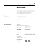


Specifications B–7
DeviceNet Communications Module
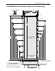
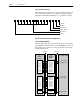
The following fugure shows how the I/O image table for the
programmable controller relates to the 1336 REGEN Converter
when a Flex I/O Module is used.
Scanner
Output Mapping
(Write)
Input Mapping
(Read)
Input Mapping
(Read)
1203–Gx5
DeviceNet to SCANport
Word 0 Logic Command
Word 1 Reference
Word 2 Not Used
Word 3 Not Used
Word 4 Not Used
Word 5 Not Used
Word 6 Not Used
Word 7 Not Used
Word 8 Not Used
Word 9 Not Used
Word 0 Logic Status
Word 1 Feedback
Word 2 Not Used
Word 3 Not Used
Word 4 Not Used
Word 5 Not Used
Word 6 Not Used
Word 7 Not Used
Word 8 Not Used
Word 9 Not Used
1336 REGEN Converter
Logic Command
Bus Voltage Reference
Logic Status
Actual Bus Voltage
SCANport
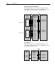
PLC, SLC
or PC
Message
Buffers
Message Handler