
Instruction Manual


B–4 Specifications
Logic Command Structure
This information provides the control logic information that is sent
to the converter through the logic controllers output image table
when the Communication Module is set to control the converter.
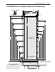
Typical PLC Communications Configurations
SLC to SCANport Module
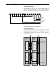
The following fugure shows how the I/O image table for the SLC
programmable controller relates to the 1336 REGEN Converter. In
this example, the converter is connected to channel 1 of the SLC
module in basic mode.
Bit 12 Bit 11 Bit 10 Bit 9 Bit 8 Bit 7 Bit 6 Bit 5 Bit 4 Bit 3 Bit 2 Bit 1 Bit 0Bit 13Bit 14Bit 15
Disable
Enable
Not Used
Not Used
Clear Faults
Reset
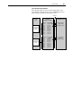
SLC
I/O Image
Output Image
O:1.2
O:1.3
O:1.8
O:1.9
O:1.10
O:1.11
O:1.12
O:1.13
O:1.14
O:1.15
Input Image
I:1.2
I:1.3
I:1.8
I:1.9
I:1.10
I:1.11
I:1.12
I:1.13
I:1.14
I:1.15
Input Image
SLC
SCANport
Module
Logic Command
Reference
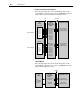
Not Used
Not Used
Not Used
Not Used
Not Used
Not Used
Not Used
Not Used
Logic Status
Feedback
Not Used
Not Used
Not Used
Not Used
Not Used
Not Used
Not Used
Not Used
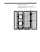
1336 REGEN Converter
Logic Command
Bus Voltage Reference
Logic Status
Actual Bus Voltage
Message Handler
Message
Buffers
Backplane SCANport