336 REGEN Line Regeneration Package Firmware Version 3.
Important User Information Solid-State equipment has operational characteristics differing from those of electromechanical equipment. “Safety Guidelines for the Application, Installation and Maintenance of Solid-State Controls” (Publication SGI-1.1) describes some important differences between solid-state equipment and hard-wired electromechanical devices.
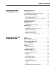
Table of Contents Line Regeneration Package Overview What This Publication Provides . . . . . . . . . . . . . . . . . . . . . . . . . . . . . 1-1 What This Product Provides . . . . . . . . . . . . . . . . . . . . . . . . . . . . . . . . 1-1 1336 REGEN Line Regeneration Package Components . . . . . . . . . 1-1 How to Choose a Mode of Operation . . . . . . . . . . . . . . . . . . . . . . . . . 1-2 The Regenerative DC Bus Supply Mode . . . . . . . . . . . . . . . . . . . . . 1-2 The Regenerative Brake Mode .
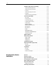
ii 120VAC Precharge and Converter Wiring . . . . . . . . . . . . . . . . . . . . 2-12 120VAC Current Requirements . . . . . . . . . . . . . . . . . . . . . . . . . . . 2-12 120VAC Converter Connections . . . . . . . . . . . . . . . . . . . . . . . . . . . 2-13 Converter . . . . . . . . . . . . . . . . . . . . . . . . . . . . . . . . . . . . . . . . . . . . 2-13 120VAC Precharge Connections . . . . . . . . . . . . . . . . . . . . . . . . . . 2-14 Precharge . . . . . . . . . . . . . . . . . . . . . . . . . .
iii Input Power Conditioning . . . . . . . . . . . . . . . . . . . . . . . . . . . . . . . . . . 3-8 Input Fusing . . . . . . . . . . . . . . . . . . . . . . . . . . . . . . . . . . . . . . . . . . . . . 3-9 Customer Supplied Fusing . . . . . . . . . . . . . . . . . . . . . . . . . . . . . . . . 3-9 1336 REGEN Precharge Fusing . . . . . . . . . . . . . . . . . . . . . . . . . . . . 3-9 380-480VAC Power Wiring . . . . . . . . . . . . . . . . . . . . . . . . . . . . . . . .
iv Programming . . . . . . . . . . . . . . . . . . . . . . . . . . . . . . . . . . . . . . . . . . . 3-33 Overview . . . . . . . . . . . . . . . . . . . . . . . . . . . . . . . . . . . . . . . . . . . . . 3-33 Conventions . . . . . . . . . . . . . . . . . . . . . . . . . . . . . . . . . . . . . . . . . . 3-33 Parameter Decriptions . . . . . . . . . . . . . . . . . . . . . . . . . . . . . . . . . . 3-34 Troubleshooting Overview . . . . . . . . . . . . . . . . . . . . . . . . . . . . . . . . . . . . . . .
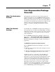
Chapter 1 Line Regeneration Package Overview What This Publication Provides This publication provides layout, sizing, wiring, startup and diagnostic information for the 1336 REGEN Line Regeneration Package, including Converter, Precharge Unit, 1321 Line Reactor, and Line Filter (when required). To ensure successful installation and operation, the material presented must be thoroughly read and understood before proceeding.
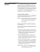
1–2 Line Regeneration Package Overview How to Choose a Mode of Operation Several characteristics influence the choice of an operating mode for a given application. The 1336REGEN Line Regeneration Package can be used with any 380-480 volt drive in the 1336 family. The desired performance of the combined AC drive/Line Regeneration Package will dictate which mode of operation is best for an application.
Line Regeneration Package Overview How to Choose a Mode of Operation 1–3 The Regenerative Brake Mode In the Regenerative Brake Mode, the 1336 REGEN Line Regeneration Package removes energy from the DC bus of a standard 1336 AC drive back to the utility. 1. When the connected AC drive is motoring, it receives energy directly from the three-phase AC line through its input terminals and diode bridge. 2.
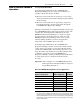
1–4 Line Regeneration Package Overview 1336 REGEN Frame Designations Allen-Bradley uses frame designations to identify the various sizes of standard and configured drives. Throughout this manual, frame sizes for 1336 REGEN Converter and Precharge Units may be used instead of AC input kW or Amp ratings. Catalog Number Explanation 1336 REGEN Converter Rating 1336 REGEN Precharge Rating Frame AC Reference Input kW Amp Rating Frame AC Reference Input kW Amp Rating B 38.4 B C 62.3 78.2 C 62.
Line Regeneration Package Overview Nameplate Location 1–5 1336REGEN B and C Frame Converter J1 PORT 2 J4 DANGER ! RISK OF ELECTRICAL SHOCK. MORE THAN ONE DISCONNECT SWITCH MAY BE REQUIRED TO DE-ENERGIZE THE EQUIPMENT BEFORE SERVICE. DANGER ! PORT 1 ELECTRICAL SHOCK HAZARD FROM ENERGY STORAGE CAPACITORS. VERIFY LOW VOLTAGE DISCHARGE BEFORE SERVICING. SEE INSTRUCTION MANUAL. J5 J13 B Frame J15 Stopped +0.
1–6 Line Regeneration Package Overview Nameplate Location 1336REGEN D Frame Converter ! DANGER ELECTRICAL SHOCK HAZARD FROM ENERGY STORAGE CAPACITORS VERIFY LOW VOLTAGE DISCHARGE BEFORE SERVICING. SEE INSTRUCTION MANUAL. ! DANGER RISK OF SHOCK REPLACE AFTER SERVICING CAT SER 1336R-VB180CNV-AN-HAP A LIST CAT SER 1336R-VB180CNV-AN-HAP A AC INPUT AC OUTPUT KVA 119-150 – DC OUTPUT 144 VOLTS 380-480 – 735 A PH HZ 180.
Line Regeneration Package Overview Nameplate Location 1–7 1336REGEN B, C and D Frame Precharge Unit B Frame CAT SER 1336R-VB048PRE-AN A CAT SER 1336R-PRE-VB048-AN AC INPUT AC OUTPUT KVA 32-40 32-40 DC OUTPUT – VOLTS 380-480 380-480 – A 48.2 48.2 – PH HZ 3 50/60 3 50/60 – – KVA 32-40 32-40 – VOLTS 380-480 380-480 – A PH HZ 48.2 3 50/60 48.2 3 50/60 – – – UL ® IN D CO NT EQ L1 LIST ALLEN-BRADLEY ® UL ® IN D CONT EQ AB MADE IN U.S.A.
1–8 Line Regeneration Package Overview Nameplate Location Bulletin 1321 3% Line Reactors for Regenerative Brake Applications IP OO (Open) C ® ® RL-20002 Manufactured By MTE Corp. Menomonee Falls, WI A1 CAT 1321-3R200-B PART# 0.11mH 200AMPS 1th=300A A2 B1 ® C ® ® CAT 1321-3R200-B PART# 0.11mH 200AMPS lth-300A RL-20002 E66214 180-36 3 PHASE REACTOR 600V MAX 50/60 Hz B2 C1 Manufactured By MTE Corp.
Line Regeneration Package Overview Nameplate Location 1–9 Bulletin 1321 10% Line Reactors for Regenerative DC Bus Supply Applications IP OO (Open) C ® ® RL-18004 Manufactured By MTE Corp. Menomonee Falls, WI R1 CAT 1321-3LR180-B PART# 0.430mH 180AMPS lth-270A 9730 R2 S1 ® C ® ® RL-18004 E66214 180-36 3 PHASE REACTOR 600V MAX 50/60 Hz S2 T1 Manufactured By MTE Corp. Menomonee Falls, WI R1 CAT 1321-3LR180-B PART# 0.
1–10 Line Regeneration Package Overview End of Chapter
Chapter 2 Regenerative DC Bus Supply Operation Overview When properly sized, the 1336 REGEN Line Regenerative Package represents an amp rated package that can provide a DC bus to one or more common bus drives in the Regen DC Bus Supply mode. General Precautions ! ! ! ! ATTENTION: Only personnel familiar with the 1336 REGEN Line Regeneration Package and associated equipment should plan or implement the installation, start-up and subsequent maintenance of the system.
2–2 Regenerative DC Bus Supply Operation Regenerative DC Bus Supply Layout CAT SER 1336R-PRE-VB180-AN A D9 LISTE 66X Power Line Filter 1 R Conduit/4-Wire Cable S LS S T LT T R OUT OUT S OUT T 1 3 5 L1 L2 L3 R1 IN – VOLTS 380-480 380-480 – A PH HZ 180.4 3 50/60 180.
Regenerative DC Bus Supply Operation Regenerative DC Bus Supply Sizing 2–3 The 1336 REGEN Package The following steps should be taken to size the 1336 REGEN Package for Regenerative DC Bus Supply Operation. 1. The 1336 REGEN Converter, 1336 REGEN Precharge and 1321 10% Line Reactor must be sized as a package, with all components having the same nameplate amp rating. 2.
2–4 Regenerative DC Bus Supply Operation Input Fusing ! ATTENTION: 1336 REGEN equipment does not provide input power short circuit fusing. Branch circuit breakers or disconnect switches cannot provide this level of protection for converter and precharge unit components. Specifications for the recommended fuse size and type to provide input power protection against short circuits at the Converter or Precharge Unit is listed below.
Regenerative DC Bus Supply Operation 380-480VAC Power Wiring 2–5 Unbalanced Distribution Systems The 1336 REGEN Package is designed to operate on 3Ø supply systems whose line voltages are symmetrical. Surge suppression devices are included to protect the drive from lightning induced overvoltages between line and ground.
2–6 Regenerative DC Bus Supply Operation 380-480VAC Power Wiring Grounding All 1336 REGEN components must be connected to system ground at the PE power ground terminal provided. Ground impedance must conform to the requirements of national and local industrial safety regulations (NEC, VDE 0160, BSI, etc.), and should be inspected and tested at appropriate intervals. In any cabinet, a single low-impedance ground point or ground bus bar should be used.
Regenerative DC Bus Supply Operation 380-480VAC Power Wiring LINE FILTER PRECHARGE UNIT LINE REACTOR 2–7 CONVERTER Input Term. Output Term. Input Term. Output Term. Input Term. Output Term. Input Term. 380-480VAC Power Connections 380-480VAC input and output power connections are made as shown in Figure 2.4 through Figure 2.8.
2–8 Regenerative DC Bus Supply Operation 380-480VAC Power Wiring B and C Frames Precharge CAT SER 1336R-PRE-VB048-AN A D9 LISTE 66X AC INPUT AC OUTPUT KVA 32-40 32-40 DC OUTPUT – VOLTS 380-480 380-480 – A PH HZ 48.2 3 50/60 48.2 3 50/60 – – – UL ® IN D L1 L2 C ONT EQ ® D9 LISTE 66X C ALLEN-BRADLEY REFER TO USER MANUAL FOR INSTALLATION ISNTRUCTIONS UL ® IN D C ONT EQ AB MADE IN U.S.A.
Regenerative DC Bus Supply Operation 2–9 380-480VAC Power Wiring Converter B Frame J1 PORT 2 J4 ! DANGER ! DANGER RISK OF ELECTRICAL SHOCK. MORE THAN ONE DISCONNECT SWITCH MAY BE REQUIRED TO DE-ENERGIZE THE EQUIPMENT BEFORE SERVICE. PORT 1 ELECTRICAL SHOCK HAZARD FROM ENERGY STORAGE CAPACITORS. VERIFY LOW VOLTAGE DISCHARGE BEFORE SERVICING. SEE INSTRUCTION MANUAL. J5 J13 J15 Stopped +0.
2–10 Regenerative DC Bus Supply Operation 380-480VAC Power Wiring Converter ! DANGER ELECTRICAL SHOCK HAZARD FROM ENERGY STORAGE CAPACITORS VERIFY LOW VOLTAGE DISCHARGE BEFORE SERVICING. SEE INSTRUCTION MANUAL. ! DANGER RISK OF SHOCK REPLACE AFTER SERVICING CAT SER 1336R-VB180CNV-AN-HAP A D9 LISTE 66X AC INPUT AC OUTPUT KVA 119-150 – DC OUTPUT 144 VOLTS 380-480 – 735 A PH HZ 180.
Regenerative DC Bus Supply Operation 380-480VAC Power Wiring 2–11 380-480VAC Power Connection Specifications 1. Use 75ºC Copper Wire Only. 2. Listed wires sizes are maximum/minimum wire sizes that the terminals will accept — Not recommendations. 1336 REGEN POWER LINE FILTER RATING MAX/MIN WIRE SIZE mm 2 (AWG) MAX TORQUE N-m (lb-in) 48A 13.3/0.5 (6/20) — Single Conductor 1.70 (15) 78A 26.7/0.8 (3/18) — Single Conductor 5.65 (50) 180A 127.0/2.1 (250MCM/14) — Single Conductor 6.00 (52) 67.4/2.
2–12 Regenerative DC Bus Supply Operation 120VAC Precharge and Converter Wiring ATTENTION: 1336 REGEN equipment does not provide 120VAC short circuit fusing. Branch circuit breakers or disconnect switches cannot provide this level of protection for converter and precharge unit components. Short circuit fusing should be sized and typed in accordance with National Codes and standards (NEC, CENELEC, etc.) and any additional local codes.
Regenerative DC Bus Supply Operation 120VAC Precharge and Converter Wiring 2–13 120VAC Converter Connections 120VAC input and output power connections are made to D Frame Converters as shown below. Converter ! DANGER ELECTRICAL SHOCK HAZARD FROM ENERGY STORAGE CAPACITORS VERIFY LOW VOLTAGE DISCHARGE BEFORE SERVICING. SEE INSTRUCTION MANUAL.
2–14 Regenerative DC Bus Supply Operation 120VAC Precharge and Converter Wiring 120VAC Precharge Connections 120VAC input and output connections are made to B-D Frame Precharge Units as shown below. CAT SER 1336R-PRE-VB180-AN Precharge A D LISTE 966X AC INPUT AC OUTPUT KVA 119-150 119-150 DC OUTPUT – VOLTS 380-480 380-480 – A PH HZ 180.4 3 50/60 180.
Regenerative DC Bus Supply Operation 2–15 Control and Signal Wiring Sync Cable The sync cable that is shipped with the 1336 REGEN Precharge unit connects the required startup, diagnostic and control signals between the 1336 REGEN Converter Control Board and the 1336 REGEN Precharge Board. The ribbon cable shield provided at the converter end must be connected to the Control Board Shield Connector J14 as shown in Figure 2.13 to maintain signal integrity.
2–16 Regenerative DC Bus Supply Operation Control and Signal Wiring Precharge Board J2 R S F1 T R 1 F2 S 1 T 1 F3 TB Precharge 1 P7 CAT SER 1336R-PRE-VB180-AN A D LISTE 966X AC INPUT AC OUTPUT KVA 119-150 119-150 DC OUTPUT – VOLTS 380-480 380-480 – A PH HZ 180.4 3 50/60 180.4Y 3 50/60 – – – UL ® IN D C ONT EQ ® D9 LISTE 66X C REFER TO USER MANUAL FOR INSTALLATION INSTRUCTIONS ALLEN-BRADLEY UL ® IN D C ONT EQ AB MADE IN U.S.A.
Regenerative DC Bus Supply Operation 2–17 Control and Signal Wiring Converter Control Board J9 Converter NOT USED 1 J7 NOT USED J1 20 1 NOT USED J2 1 7 R4 ! DANGER U FA S1 D M M CO S4 US D AT ST 3 LE DS J3 AB EN S2 D V 24 0V 12 0 J1 3 J1 1 V 24 NOT USED UG DB TS PU IN SY SHCAB NC IEL LE D C SY W ONT NC IRI RO CA NG L BL E DI G WI INPUITAL RI T NG D O IG WI UTP ITAL RI UT NG V 24 0V 12 1 J1 LD IE SH 4 J1 ! DANGER RISK OF SHOCK REPLACE AFTER SERVICING LT 0V 12 8 J1 ELECTRICAL SHO
2–18 Regenerative DC Bus Supply Operation Control and Signal Wiring Control Board Connections All customer control and signal wiring is made to quick-connect terminal blocks J15 and J16. The maximum/minimum wire sizes accepted by J15 & J16 is 3.3/ 0.6mm2 (12/30AWG). Maximum torque is 0.79N-m (7lb.-in.). Recommended control/signal wire is: • Belden 8760 (or equivalent) — 0.750mm2 (18AWG), Twisted Pair, Shielded. • Belden 8770 (or equivalent) — 0.750mm2 (18AWG), 3-Conductor, Shielded.
Regenerative DC Bus Supply Operation Control and Signal Wiring 2–19 Digital Input Signals ! ATTENTION: Ensure that all jumpers on the 1336 REGEN Converter Control Board are set correctly prior to applying AC power to the board. Applying 120VAC to the digital inputs when jumpers J10, J11 or J18 are set to 24VDC will permanently damage the Converter Control Board. Important: Customer EXTERNAL FAULT and ENABLE circuits must be connected to J15 and at logic high for the 1336 REGEN Converter to operate.
2–20 Regenerative DC Bus Supply Operation Control and Signal Wiring Important: Fuse R47 is self-resetting and will open should a low impedance or short circuit occur at J15 during 24VDC operation. Should a fault occur, allow (1) minute after removal of power from the Converter Control Board for R47 to cool before reapplying power. Important: For Regenerative DC Bus Supply applications, the 1336 REGEN Line Regeneration Package will be used with one or more common bus drives.
Regenerative DC Bus Supply Operation Control and Signal Wiring 2–21 Interlocking 1336 REGEN Enable with AC Drive Enable It may be desirable to interlock the 1336 REGEN Enable Output with the Enable Input on the connected 1336 PLUS, 1336 PLUSII, 1336 IMPACT or 1336 FORCE AC drive. This will keep the AC drive from starting if the 1336 REGEN Converter is not enabled, and will also remove the Enable signal from the AC drive if the 1336 REGEN Converter is faulted.
2–22 Regenerative DC Bus Supply Operation Adapter Definitions 1336 REGEN Converter Control Board J3 1 PO R T J16 2 1 9 PO R T 1 L E S When the Converter mounted Programming Only HIM is supplied, it is connected as adapter 1 as detailed in Figure 2.14. Figure 2.14 also shows the maximum distance allowed between devices. J15 C S E Serial communication devices such as the HIM that are connected to the 1336 REGEN Converter are identified by SCANport serial communications as adapters.
Regenerative DC Bus Supply Operation Human Interface Module 2–23 HIM Description When the converter mounted HIM is supplied, it will be connected as Adapter 1 and visible from the front of the converter.
2–24 Regenerative DC Bus Supply Operation Programming Flow Chart Default Display or or or or choose mode Display read only Process read/write Program read/write EEProm read/write Process Var1 1 - Bus VReg 2 - Bus Volt 3 - Regen L Save Values ➊ Process Var2 0 - Blanks Line 1 - Bus VReg 2 - Bus Volt 3 - Regen L Drive ➔ HIM ➋ Recall Values ➊ Reset Defaults HIM ➔ Drive ➋ parameters ➊ Reserved for future use. ➋ HIM will indicate Drive, but download will be to or from 1336 REGEN Converter.
Regenerative DC Bus Supply Operation Regenerative DC Bus Supply Startup 2–25 Overview The following procedure describes how to startup the 1336 REGEN Line Regeneration Package and connected common bus drive when used for Regenerative DC bus supply applications. Included are typical checks to assure proper operation. The selection information contained in Chapter 1 must be read and understood before proceeding.
2–26 Regenerative DC Bus Supply Operation Regenerative DC Bus Supply Startup Initial Operation Important: For Regenerative DC Bus Supply applications, the 1336 REGEN Line Regeneration Package will be used with one or more common bus drives (see Figure 2.1). It is recommend that the fault relay on the 1336 REGEN Converter Control board be interconnected into the common bus drive(s) control logic. This will allow coordination the Regenerative DC Bus Supply faults with the common bus drive. 1.
Regenerative DC Bus Supply Operation Regenerative DC Bus Supply Startup 7. From the status display, press Choose Mode Display 8. Press the or displayed. 2–27 or any other key. will be displayed. until C h o o s e M o d e is until E E P r o m is EEProm 9. Press 10.Press the displayed. 11.Press or Reset Defaults to restore all parameters to their original factory settings. 12.Press once to exit back to the status display.
2–28 Regenerative DC Bus Supply Operation Programming Overview The 1336 REGEN Line Regeneration Package is designed so that factory default parameter settings allow it to operate satisfactorily under a wide variety of load and utility conditions. Important: The 1336 REGEN Package has been shipped from the factory with Parameter 1 set to the Regenerative Brake Mode of operation. For Regenerative DC Bus Supply applications, this parameter must be reset as described in “Operational Mode” on page 2-29.
Regenerative DC Bus Supply Operation 2–29 Programming Operational Mode Operational Mode 1 XXXX0000 Parameter No. Display Units Parameter Type Factory Default Regen Brake Mode 1 bits Read/Write XXXXX000 Sets the 1336 REGEN Line Regeneration Package mode of operation. The modes are defined by the last (3) bits of a 16 bit word. To set the mode, first stop the 1336 REGEN Converter, set the mode, then re-enable the converter.
2–30 Regenerative DC Bus Supply Operation Programming Actual Bus Voltage Bus Volts Act. 5 735.0 VOLT Parameter No. Display Units Parameter Type Drive Units Displays the actual voltage on the DC bus in DC volts. 5 Volts Read Only 1 = 0.1V Bus VReg Ref. 735.0 VOLT Bus Voltage Reference 6 This parameter sets the DC bus voltage. It allows the DC Bus voltage to be set to 2-18% higher than the DC Base volts while the 1336 REGEN Converter is enabled. 6 Parameter No.
Regenerative DC Bus Supply Operation 2–31 Programming Motoring Cur Lim 12 +150 % Parameter No. Display Units Parameter Type Factory Default Min/Max Value Drive Units 12 % Read/Write 150% 0/150 100 = 4096 Regen Curr Limit 13 -150 % Parameter No. Display Units Parameter Type Factory Default Min/Max Value Drive Units 13 % Read/Write -150% -150/0 100 = 4096 IOC SW Trip 192 % Parameter No.
2–32 Regenerative DC Bus Supply Operation Programming BOV SW Trip 130 % Display Units Parameter Type Factory Default Display Units Parameter Type Factory Default Display Units Parameter Type Factory Default For 380VAC input Line Regeneration Packages, DC BASE volts = 537V. For 460VAC input Line Regeneration Packages, DC BASE volts = 650V. This parameter sets a software over voltage trip point that is active when the 1336 REGEN Converter is not enabled.
Regenerative DC Bus Supply Operation 2–33 Programming LUV Trip 1 85 % Display Units Parameter Type Factory Default 75/90% ACBASE➊ Drive Units LUV Trip 2 60 % Parameter No. Display Units Parameter Type Factory Default Min/Max Value Drive Units 20 20 % Read/Write 85% ACBASE➊ Parameter No. Min/Max Value AC Line Undervoltage Trip Level 1 (Not Enabled) Display Units Parameter Type Factory Default Min/Max Value Drive Units ➊ For 380VAC input Line Regeneration Packages, AC BASE volts = 380V.
2–34 Regenerative DC Bus Supply Operation Programming Port Enable Mask XX X X X 1 1 1 23 23 Bits Read/Write 111 0/7 N/A Parameter No. Display Units Parameter Type Factory Default Min/Max Value Drive Units Port Enabled Mask This parameter sets the ability of a SCANport device to issue enable commands. The commands are defined by the first (3) bits of a 16 bit word. The [Port Enable Mask] may be set while the 1336 REGEN Converter is enabled.
Regenerative DC Bus Supply Operation 2–35 Programming Fault Select1 27 XXX11100 Parameter No. Display Units Parameter Type Factory Default Min/Max Value Drive Units 27 Bits Read/Write 11100 N/A N/A HIM Display Prm 28 5 Parameter No. Display Units Parameter Type Factory Default Min/Max Value Drive Units 28 Number Read/Write 5 1/32 N/A Fault Select 1 This parameter enables or disables faults as defined by the first (5) bits of a (16) bit word.
2–36 Regenerative DC Bus Supply Operation End of Chapter
Chapter 3 Regenerative Brake Operation Overview The 1336 REGEN Line Regeneration Package represents an amp rated package that can remove energy from the DC bus of a 1336 PLUS, PLUSII, FORCE or IMPACT AC drive and send it back to the utility. When properly sized with one or more standard 1336 PLUS, PLUSII, FORCE or IMPACT AC drives, Regenerative Brake Operation provides an energy efficient alternative solution to dynamic braking.
3–2 Regenerative Brake Operation Regenerative Brake Layout CAT SER 1336R-PRE-VB180-AN A D9 LISTE 66X AC INPUT AC OUTPUT KVA 119-150 119-150 DC OUTPUT – VOLTS 380-480 380-480 – A PH HZ 180.4 3 50/60 180.4 3 50/60 – – – UL ® IN D C ONT EQ ® D LISTE 966X C ALLEN-BRADLEY REFER TO USER MANUAL FOR INSTALLATION INSTRUCTIONS UL ® IN D C ONT EQ AB MADE IN U.S.A.
Regenerative Brake Operation Power-up Sequence for Regenerative Brakes and B Frame AC Drives 3–3 When using a 1336 REGEN Line Regeneration Package with a B Frame 1336 PLUS, PLUSII, IMPACT, or FORCE, a special power-up sequence is needed to avoid clearing the AC line fuses on the input of the AC drive or the DC bus fuses between the drive and the Regenerative Brake. These fuses will clear if both the 1336 REGEN Package and the connected B Frame AC drive are powered up from the AC supply simultaneously.
3–4 Regenerative Brake Operation Regenerative Brake Sizing The following steps should be taken to size a 1336 REGEN Line Regeneration Package for Regenerative Brake Operation. 1. The 1336 REGEN Converter and 1336 REGEN Precharge unit must be sized as a package, with both components having the same nameplate amp rating. 2. In the Regenerative Brake configuration, the 1336 REGEN Line Regeneration Package removes energy from the DC bus of a standard drive and returns it back to the utility system.
Regenerative Brake Operation Regenerative Brake Sizing 3–5 6. Determine the required percent of braking torque (TQ%). TQ% = TQ B × 100 —————— TQ M Where TQ B = The Required Braking Torque TQ M = The Rated Motor Torque 7. Determine the peak braking horsepower (HP2). HP2 = TQ B × N1 —————— 5250 Where TQ B = N1 = The Required Braking Torque The Maximum Motor Speed 8. Calculate the peak AC line current (I 1).
3–6 Regenerative Brake Operation Regenerative Brake Sizing This is the peak current the 1336 REGEN Package can return to the AC utility. For any regenerative application, the peak AC current calculated in Step 8 (I 1), must be less than the peak current calculated in Step 9 (I OL). Because I 1 is greater than the rated current of the 1336 REGEN Package, the 1336 REGEN Package will be operating at its overload region for some portion of the application cycle.
Regenerative Brake Operation Regenerative Brake Sizing 3–7 Additional Requirements In addition to satisfying the peak current requirements, the application must satisfy the duty cycle limitations of the 1336 REGEN Package. After operating in the overload region, the 1336 REGEN Package must operate at or below rated current for some period of time before it can be overloaded again.
3–8 Regenerative Brake Operation Regenerative Brake Sizing The table below summarizes the maximum deceleration times that the 1336 REGEN Package can provide with various peak currents when decelerating a load. As long as the peak overload current is less than 150% and maximum deceleration time is less than that listed in the table, the 1336 REGEN Package will not trip on overload. In general, if the load is decelerating to zero speed, there is no limit on the available duty cycle.
Regenerative Brake Operation 3–9 Input Fusing ! ATTENTION: 1336 REGEN equipment does not provide input power short circuit fusing. Branch circuit breakers or disconnect switches cannot provide this level of protection for converter and precharge unit components. Specifications for the recommended fuse size and type to provide input power protection against short circuits at the Converter or Precharge Unit is listed below.
3–10 Regenerative Brake Operation 380-480VAC Power Wiring Unbalanced Distribution Systems The 1336 REGEN Line Regeneration Package is designed to operate on 3Ø systems supply systems whose line voltages are symmetrical. Surge suppression devices are included to protect the drive from lightning induced overvoltages between line and ground.
Regenerative Brake Operation 380-480VAC Power Wiring 3–11 Grounding All 1336 REGEN components must be connected to system ground at the PE power ground terminal provided. Ground impedance must conform to the requirements of national and local industrial safety regulations (NEC, CENELEC, etc.), and should be inspected and tested at appropriate intervals. In any cabinet, a single low-impedance ground point or ground bus bar should be used. All circuits should be grounded independently and directly.
3–12 Regenerative Brake Operation 380-480VAC Power Wiring 380-480VAC Power Connections 380-480VAC input and output power connections are made as shown in Figure 3.5 through Figure 3.8. ATTENTION: 1336 REGEN equipment will not be properly synchronized unless correct Precharge-to-Line Reactor-to-Converter AC power connections are maintained. Failure to maintain correct phase-related connections will result in equipment malfunction and/or failure. ! PRECHARGE UNIT LINE REACTOR CONVERTER Input Term.
Regenerative Brake Operation 3–13 380-480VAC Power Wiring B and C Frames Precharge CAT SER 1336R-PRE-VB048-AN A D9 LISTE 66X AC INPUT AC OUTPUT KVA 32-40 32-40 DC OUTPUT – VOLTS 380-480 380-480 – A PH HZ 48.2 3 50/60 48.2 3 50/60 – – – UL ® IN D L1 L2 C ONT EQ ® D9 LISTE 66X C ALLEN-BRADLEY REFER TO USER MANUAL FOR INSTALLATION ISNTRUCTIONS UL ® IN D C ONT EQ AB MADE IN U.S.A.
3–14 Regenerative Brake Operation 380-480VAC Power Wiring Converter B Frame J1 PORT 2 J4 DANGER ! RISK OF ELECTRICAL SHOCK. MORE THAN ONE DISCONNECT SWITCH MAY BE REQUIRED TO DE-ENERGIZE THE EQUIPMENT BEFORE SERVICE. DANGER ! PORT 1 ELECTRICAL SHOCK HAZARD FROM ENERGY STORAGE CAPACITORS. VERIFY LOW VOLTAGE DISCHARGE BEFORE SERVICING. SEE INSTRUCTION MANUAL. J5 J13 J15 Stopped +0.
Regenerative Brake Operation 3–15 380-480VAC Power Wiring Converter ! DANGER ELECTRICAL SHOCK HAZARD FROM ENERGY STORAGE CAPACITORS VERIFY LOW VOLTAGE DISCHARGE BEFORE SERVICING. SEE INSTRUCTION MANUAL. ! DANGER RISK OF SHOCK REPLACE AFTER SERVICING CAT SER 1336R-VB180CNV-AN-HAP A D9 LISTE 66X AC INPUT AC OUTPUT KVA 119-150 – DC OUTPUT 144 VOLTS 380-480 – 735 A PH HZ 180.
3–16 Regenerative Brake Operation 380-480VAC Power Wiring 380-480VAC Power Connection Specifications 1. Use 75ºC Copper Wire Only. 2. Listed wires sizes are maximum/minimum wire sizes that the terminals will accept — Not recommendations. 1336 REGEN PRECHARGE UNIT RATING MAX/MIN WIRE SIZE mm 2 (AWG) MAX TORQUE N-m (lb-in) B Frame 13.3/0.5 (6/20) — Single Conductor 1.70 (15) C Frame 26.7/0.8 (3/18) — Single Conductor 5.65 (50) D Frame 127.0/2.1 (250MCM/14) — Single Conductor 6.00 (52) 67.4/2.
Regenerative Brake Operation 120VAC Precharge and Converter Wiring 3–17 ATTENTION: 1336 REGEN equipment does not provide 120VAC short circuit fusing. Branch circuit breakers or disconnect switches cannot provide this level of protection for converter and precharge unit components. Short circuit fusing should be sized and typed in accordance with National Codes and standards (NEC, CENELEC, etc.) and any additional local codes. ! 120VAC Current Requirements 1336 REGEN LINE REGENERATION PACKAGE CAT. NO.
3–18 Regenerative Brake Operation 120VAC Precharge and Converter Wiring 120VAC Converter Connections 120VAC input and output power connections are made as shown below. Converter ! DANGER ELECTRICAL SHOCK HAZARD FROM ENERGY STORAGE CAPACITORS VERIFY LOW VOLTAGE DISCHARGE BEFORE SERVICING. SEE INSTRUCTION MANUAL. ! DANGER RISK OF SHOCK REPLACE AFTER SERVICING CAT SER 1336R-VB180CNV-AN-HAP A D9 LISTE 66X AC INPUT AC OUTPUT DC OUTPUT KVA 119-150 – 144 VOLTS 380-480 – 735 A PH HZ 180.
Regenerative Brake Operation 120VAC Precharge and Converter Wiring 3–19 120VAC Precharge Connections 120VAC input and output connections are made to B-D Frame Precharge Units as shown below. CAT SER 1336R-PRE-VB180-AN Precharge A D LISTE 966X AC INPUT AC OUTPUT KVA 119-150 119-150 DC OUTPUT – VOLTS 380-480 380-480 – A PH HZ 180.4 3 50/60 180.
3–20 Regenerative Brake Operation Control and Signal Wiring Sync Cable The sync cable that is shipped with the 1336 REGEN Precharge unit connects the required startup, diagnostic and control signals between the 1336 REGEN Converter Control Board and the 1336 REGEN Precharge Board. The ribbon cable shield provided at the converter end must be connected to the Control Board Shield Connector J14 as shown in Figure 3.13 to maintain signal integrity.
Regenerative Brake Operation 3–21 Control and Signal Wiring Precharge Board J2 R S F1 T R 1 F2 S 1 T 1 F3 TB Precharge 1 P7 CAT SER 1336R-PRE-VB180-AN A D LISTE 966X AC INPUT AC OUTPUT KVA 119-150 119-150 DC OUTPUT – VOLTS 380-480 380-480 – A PH HZ 180.4 3 50/60 180.4Y 3 50/60 – – – UL ® IN D C ONT EQ ® D9 LISTE 66X C REFER TO USER MANUAL FOR INSTALLATION INSTRUCTIONS ALLEN-BRADLEY UL ® IN D C ONT EQ AB MADE IN U.S.A.
3–22 Regenerative Brake Operation Control and Signal Wiring Converter Control Board J9 Converter NOT USED 1 J7 NOT USED J1 20 1 NOT USED J2 1 7 R4 ! DANGER U FA S1 D M M CO S4 US D AT ST 3 LE DS J3 AB EN S2 D V 24 0V 12 0 J1 3 J1 1 V 24 NOT USED UG DB TS PU IN SY SHCAB NC IEL LE D C SY W ONT NC IRI RO CA NG L BL E DI G WI INPUITAL RI T NG D O IG WI UTP ITAL RI UT NG V 24 0V 12 1 J1 LD IE SH 4 J1 ! DANGER RISK OF SHOCK REPLACE AFTER SERVICING LT 0V 12 8 J1 ELECTRICAL SHOCK HAZAR
Regenerative Brake Operation Control and Signal Wiring 3–23 Control Board Connections All customer control and signal wiring is made to quick-connect terminal blocks J15 and J16. The maximum/minimum wire sizes accepted by J15 & J16 is 3.3/ 0.6mm2 (12/30AWG). Maximum torque is 0.79N-m (7lb.-in.). Recommended control/signal wire is: • Belden 8760 (or equivalent) — 0.750mm2 (18AWG), Twisted Pair, Shielded. • Belden 8770 (or equivalent) — 0.750mm2 (18AWG), 3Conductor, Shielded.
3–24 Regenerative Brake Operation Control and Signal Wiring Digital Input Signals ! ATTENTION: Ensure that all jumpers on the 1336 REGEN Converter Control Board are set correctly prior to applying AC power to the board. Applying 120VAC to the digital inputs when jumpers J10, J11 or J18 are set to 24VDC will permanently damage the Converter Control Board. Important: Customer EXTERNAL FAULT and ENABLE circuits must be connected to J15 and at logic high for the 1336 REGEN Converter to operate.
Regenerative Brake Operation Control and Signal Wiring 3–25 Important: Fuse R47 is self-resetting and will open should a low impedance or short circuit occur at J15 during 24VDC operation. Should a fault occur, allow (1) minute after removal of power from the Converter Control Board for R47 to cool before reapplying power. Important: For Regenerative Brake applications, the 1336 REGEN Package will always be used with a single 1336 AC drive.
3–26 Regenerative Brake Operation Control and Signal Wiring Interlocking 1336 REGEN Enable with AC Drive Enable It may be desirable to interlock the 1336 REGEN Enable Output with the Enable Input on the connected 1336 PLUS, 1336 PLUSII, 1336 IMPACT or 1336 FORCE AC drive. This will keep the AC drive from starting if the 1336 REGEN Converter is not enabled, and will also remove the Enable signal from the AC drive if the 1336 REGEN Converter is faulted.
Regenerative Brake Operation 3–27 Adapter Definitions Serial communication devices such as the HIM that are connected to the 1336 REGEN Converter are identified by SCANport serial communications as adapters. Depending on the communications options ordered, a number of different adapters are available.
3–28 Regenerative Brake Operation Human Interface Module HIM Description When the converter mounted HIM is supplied, it will be connected as Adapter 1 and visible from the front of the converter. The display panel provides a means of programming the 1336 REGEN Converter and viewing the various operating parameters.
Regenerative Brake Operation 3–29 Programming Flow Chart Default Display or or or or choose mode Display read only Process read/write Program read/write EEProm read/write Process Var1 1 - Bus VReg 2 - Bus Volt 3 - Regen L Save Values ➊ Process Var2 0 - Blanks Line 1 - Bus VReg 2 - Bus Volt 3 - Regen L Drive ➔ HIM ➋ Search read only Recall Values ➊ Reset Defaults HIM ➔ Drive ➋ parameters ➊ Reserved for future use.
3–30 Regenerative Brake Operation Regenerative Brake Startup Overview The following procedure describes how to startup the 1336 REGEN Line Regeneration Package and connected 1336 AC drive when used for Regenerative Brake applications. Included are typical checks to assure proper operation. The selection information contained in Chapter 1 must be read and understood before proceeding. Important: For the majority of applications there should be no need to adjust parameters.
Regenerative Brake Operation Regenerative Brake Startup 3–31 Initial Operation Important: For Regenerative Brake applications, the 1336 REGEN Package will always be used with a single 1336 AC drive. It is recommend that the fault relay on the 1336 REGEN Converter Control board be interconnected into the 1336 AC drive control logic. This will allow coordination the Regenerative Brake faults with the 1336 AC drive. 1.
3–32 Regenerative Brake Operation Regenerative Brake Startup 7. From the status display, press Choose Mode Display 8. Press the or any other key. will be displayed. or until C h o o s e M o d e is or until E E P r o m is displayed. EEProm 9. Press 10. Press the displayed. 11. Press Reset Defaults to restore all parameters to their original factory settings. 12. Press once to exit back to the status display.
Regenerative Brake Operation Programming 3–33 Overview The 1336 REGEN Package is designed so that factory default parameter settings allow it to operate satisfactorily under a wide variety of load and utility conditions. For the majority of applications there should be no need to adjust parameters. Should utility or load conditions deviate from the “normal” conditions listed in the Specifications, the following parameters have been provided to allow adjustments to factory settings.
3–34 Regenerative Brake Operation Programming Operational Mode Operational Mode 1 XXXX0000 Parameter No. Display Units Parameter Type Factory Default Regen Brake Mode 1 bits Read/Write XXXXX000 Sets the 1336 REGEN Line Regeneration Package mode of operation. The modes are defined by the last (3) bits of a 16 bit word. To set the mode, first stop the 1336 REGEN Converter, set the mode, then re-enable the converter.
Regenerative Brake Operation 3–35 Programming Actual Bus Voltage Bus Volts Act. 5 735.0 VOLT Parameter No. Display Units Parameter Type Drive Units Displays the actual voltage on the DC bus in DC volts. 5 Volts Read Only 1 = 0.1V Conduction Angle Constant Cond Angle Const 9 0.50 9 Parameter No. Display Units Parameter Type Factory Default Min/Max Value Drive Units Number Read/Write 0.50 0.50/0.55 1.
3–36 Regenerative Brake Operation Programming Cur Trip Filter 5.0 11 Parameter No. Display Units Parameter Type Factory Default Min/Max Value Drive Units 11 Number Read/Write 5 1/10 1 = 4096 Instantaneous Overcurrent Trip Filter Constant This parameter adjusts a software filter to prevent nuisance tripping due to severe, repeated and prolonged line notches and voltage sags on the utility system. The default factory setting of 5 should be adequate for the majority of line and load conditions.
Regenerative Brake Operation 3–37 Programming BOV SW Trip 130 % Display Units Parameter Type Factory Default Display Units Parameter Type Factory Default Display Units Parameter Type Factory Default For 380VAC input Line Regeneration Packages, DC BASE volts = 537V. For 460VAC input Line Regeneration Packages, DC BASE volts = 650V. This parameter sets a software over voltage trip point that is active when the 1336 REGEN Converter is not enabled.
3–38 Regenerative Brake Operation Programming LUV Trip 1 85 % Display Units Parameter Type Factory Default 75/90% ACBASE➊ Drive Units LUV Trip 2 60 % Parameter No. Display Units Parameter Type Factory Default Min/Max Value Drive Units 20 20 % Read/Write 85% ACBASE➊ Parameter No. Min/Max Value AC Line Undervoltage Trip Level 1 (Not Enabled) Display Units Parameter Type Factory Default Min/Max Value Drive Units ➊ For 380VAC input Line Regeneration Packages, AC BASE volts = 380V.
Regenerative Brake Operation 3–39 Programming Port Enable Mask XX X X X 1 1 1 23 23 Bits Read/Write 111 0/7 N/A Parameter No. Display Units Parameter Type Factory Default Min/Max Value Drive Units Port Enabled Mask This parameter sets the ability of a SCANport device to issue enable commands. The commands are defined by the first (3) bits of a 16 bit word. The [Port Enable Mask] may be set while the 1336 REGEN Converter is enabled.
3–40 Regenerative Brake Operation Programming Fault Select1 27 XXX11100 Parameter No. Display Units Parameter Type Factory Default Min/Max Value Drive Units 27 Bits Read/Write XXX11100 N/A N/A HIM Display Prm 28 5 Parameter No. Display Units Parameter Type Factory Default Min/Max Value Drive Units 28 Number Read/Write 5 1/32 N/A Fault Select 1 This parameter enables or disables faults as defined by the first (5) bits of a (16) bit word.
Chapter 4 Troubleshooting Overview Chapter 4 provides information to guide the user in troubleshooting the 1336 REGEN Line Regeneration Package. Included is a listing and description of the various faults that can occur and their code numbers as they would appear on the HIM. An additional section is included to document troubleshooting from the 1336 REGEN Converter Control Board. (3) LEDs on the Control Board provide status and fault information for the 1336 REGEN Line Regeneration Package.
4–2 Troubleshooting Troubleshooting 1336 REGEN Fault and Code Number Status ENABLE STATUS COM DS2 DS3 DS4 Bus Over Volt HW On F 1 1 Flash 1 Flash On 1 Flash 2 Flashes Flashing FAULT DS1 Fault & Code No. IOC HW F 2 Flashing Indicates Action Bus voltage has exceeded 130% of 1. Reduce the braking current limit of the connected AC drive. the rated DC bus voltage — — 537VDC for a 380VAC input. 2. Reduce regeneration demand — 650VDC for a 460VAC input.
Troubleshooting 4–3 Troubleshooting Status FAULT ENABLE STATUS COM DS1 DS2 DS3 DS4 Fault & Code No. Over Temperature On F 2 Flashes 5 Flashes Flashing 8 Indicates Action The 1336 REGEN Converter heat sink temperature has exceeded 100˚C. 1. Check fan operation. 2. Check for blocked or dirty cooling fins. 3. Confirm that the Converter’s ambient temperature is within the specifications listed in Appendix B.
4–4 Troubleshooting Troubleshooting Status FAULT ENABLE STATUS COM DS1 DS2 DS3 DS4 Fault & Code No. Indicates Action Check the phase sequence wiring between incoming power lines, in and out of the Precharge Unit and at the line reactor. On 5 Flashes 2 Flashes Flashing A phase mismatch has been detected between incoming power lines, at the 1336 REGEN Precharge Unit, or at the 1321 Line Reactor. C Verify Time Out On F 18 5 Flashes 3 Flashes Flashing Since requesting the 1336 REGEN 1.
Troubleshooting 4–5 Troubleshooting Status FAULT DS1 Fault & Code No. Illegal Drv. Type F 34 On ENABLE STATUS COM DS2 DS3 DS4 N/A N/A Flashing Indicates Action The power structure is not supported. 1. Check that the Converter Control Board and Gate Driver Board are matched and correspond to the Converter frame size. 2. Reset and re-enable by: a.Exiting to the EEProm Mode. b. Resetting defaults. c. Verifying that P1 is set to the correct operating mode. d. Resetting the Converter.
4–6 Troubleshooting Troubleshooting Status FAULT DS1 Fault & Code No. Host/DSP Handshake On ENABLE STATUS COM DS2 DS3 DS4 3 Flashes 3 Flashes Don’t Care Indicates Action Host processor and DSP handshake error. Reset and re-enable the Converter. If the fault occurs again, replace the Converter Control Board. SP1 Timeout F 48 On N/A N/A Flashing The SCANport device connected to SCANport 1 has been disconnected and the mask bit for SCANport 1 is set.
Appendix A Dimensions and Weights Appendix A provides detailed dimension information for the 1336 REGEN Line Regeneration Package. Included are: • 1336 REGEN Converter Dimensions and Weights. • 1336 REGEN Precharge Unit Dimensions and Weights. • 1321 3% Line Reactor Dimensions and Weights for Regenerative Brake Operation. • 1321 10% Line Reactor Dimensions and Weights for Regenerative DC Bus Supply Operation.
A–2 Dimensions and Weights 1336 REGEN B and C Frame Converter A E Important: Allow 152.4 mm (6.0 In.) on all sides for proper heat dissipation. Z C D Knockout Diameters ➊ Dual Knockout — 3 Places 28.6/34.9 (1.13/1.38) ➋ Single Knockout — 1 Place 22.2 (0.88) Shipping Weight B Frame — 22.7 kg (50 lbs.) C Frame — 38.6 kg (85 lbs.) Stopped +0.00 Hz Q F P B O N ➋ ➊ ➊ ➊ I J SIDE FRONT BOTTOM Mounting Holes (4) 7.0 (0.28) 7.0 (0.28) 12.7 (0.50) 12.7 (0.
Dimensions and Weights 1336 REGEN D Frame Converter A E A–3 Important: Allow 152.4 mm (6.0 In.) on all sides for proper heat dissipation. C Z D Stopped +0.00 Hz Knockout Diameters ➊ Dual Knockout — 1 Place 34.9/50.0 (1.38/1.97) ➋ Dual Knockout — 2 Places 62.7/76.2 (2.47/3.00) F B ➌ Single Knockout — 3 Places 34.9 (1.38) Shipping Weight D Frame — 108.9 kg (240 lbs.) Q O P N ➊ ➋ ➌ ➌ I K J FRONT Mounting Slots (2) 7.0 (0.28) BOTTOM SIDE 7.0 (0.28) 12.7 (0.50) 12.7 (0.
A–4 Dimensions and Weights 1336 REGEN B and C Frame Precharge Unit Important: Allow 152.4 mm (6.0 In.) on all sides for proper heat dissipation. Knockout Diameters ➊ Dual Knockout — 3 Places 28.6/34.9 (1.125/1.375) Shipping Weight B and C Frame — 9.1 kg (20 lbs.) A C H D E CAT SER 1336R-PRE-VB048-AN A LIST Mounting Slots (2) 7.0 (0.28) AC INPUT AC OUTPUT KVA 32-40 32-40 DC OUTPUT – VOLTS 380-480 380-480 – A PH HZ 48.2 3 50/60 48.
Dimensions and Weights 1336 REGEN D Frame Precharge Unit A–5 Important: Allow 152.4 mm (6.0 In.) on all sides for proper heat dissipation. Knockout Diameters ➊ Dual Knockout — 2 Places 62.7/76.2 (2.47/3.00) ➋ Single Knockout — 1 Place 34.9 (1.38) Shipping Weight D Frame — 18.6 kg (41 lbs.) A C H D E CAT SER 1336R-PRE-VB180-AN A D LISTE 966X Mounting Slots (2) 7.0 (0.28) AC INPUT AC OUTPUT KVA 119-150 119-150 DC OUTPUT – VOLTS 380-480 380-480 – A PH HZ 180.4 3 50/60 180.
A–6 Dimensions and Weights 1321 48 and 78A 3% Line Reactor Important: Allow 152.4 mm (6.0 In.) on all sides for proper heat dissipation. A D Dia. C ® ® CAT 1321-3R55-B PART# 0.50mH 55AMPS 1th=82.5A RL-05502 Manufactured By MTE Corp. Menomonee Falls, WI A1 A2 B1 ® E66214 55-36 3 PHASE REACTOR 600V MAX 50/60 Hz B2 C1 E C2 Dia. G B SIDE TOP END COVER F C CAT 1321-3RA200-B Part# 3 Phase Reactors L 0.
Dimensions and Weights 1321 180A 3% Line Reactor A–7 Important: Allow 152.4 mm (6.0 In.) on all sides for proper heat dissipation. A D Dia. A1 ® RL-20002 Manufactured By MTE Corp. Menomonee Falls, WI A1 A2 B1 B1 C1 C ® CAT 1321-3R200-B PART# 0.11mH 200AMPS 1th=300A ® E66214 180-36 3 PHASE REACTOR 600V MAX 50/60 Hz B2 C1 C2 E Dia. G B A2 C2 B2 SIDE TOP END COVER F C CAT 1321-3RA200-B Part# 3 Phase Reactors L 0.
A–8 Dimensions and Weights 1321 48 and 78A 10% Line Reactor E D A Important: Allow 152.4 mm (6.0 In.) on all sides for proper heat dissipation. C E Dia. C ® ® CAT 1321-3LR180-B PART# 0.430mH 180AMPS lth-270A 9730 RL-18004 Manufactured By MTE Corp. Menomonee Falls, WI R1 R2 S1 ® F E66214 180-36 3 PHASE REACTOR 600V MAX 50/60 Hz S2 T1 T2 G Dia. R1 B R2 S1 S2 S1 S2 I SIDE TOP END COVER H C CAT 1321-3LRA180-B Part# 3 Phase Reactors L 0.
Dimensions and Weights 1321 180A 10% Line Reactor E D A A–9 Important: Allow 152.4 mm (6.0 In.) on all sides for proper heat dissipation. C E Dia. R1 ® Manufactured By MTE Corp. Menomonee Falls, WI R1 CAT 1321-3LR180-B PART# 0.430mH 180AMPS lth-270A 9730 R2 S1 S2 S1 T1 C ® RL-18004 ® E66214 180-36 3 PHASE REACTOR 600V MAX 50/60 Hz T1 T2 Dia. FG I B R2 T2 S2 SIDE TOP END CAT 1321-3LRA180-B Part# 3 Phase Reactors L 0.
A–10 Dimensions and Weights 1321 Power Line Filter All ratings are Open (IP00). 279.4 (11.00) 279.4 (11.00) 8.0 (0.32) Dia. – 4 Places – TOP 254.0 (10.00) 304.8 (12.00) 330.2 (13.
Dimensions and Weights A–11 1336 REGEN B Frame Through-the-Back Heat Sink Mounting 267.2 1 (10.52) 6.35 (0.25) 244.4 (9.62) 2.54 (0.10) 435.4 1 (17.14) 257.1 (10.12) 415.3 (16.35) 410.2 (16.15) 308.6 (12.15) Cutout as Viewed from INSIDE Enclosure 283.2 (11.15) 1 Shading indicates approximate size of drive inside enclosure. 127.0 (5.00) All Dimensions in Millimeters and (Inches) 8 Required 4.3 (0.171) Dia. for 10-32 x 12.7 (0.5) Self-Tap – 4.0 (0.159) for 10-32 x 12.7 (0.
A–12 Dimensions and Weights 1336 REGEN C Frame Through-the-Back Heat Sink Mounting 303.8 1 (11.96) 282.5 (11.12) 4.8 (0.19) 273.1 (10.75) 4.8 (0.19) 635.0 (25.00) Cutout 644.7 (25.38) 508.0 (20.00) 660.4 1 (26.00) 381.0 (15.00) 254.0 (10.00) 12 Required 4.3 (0.171) Dia. for 10-32 4.0 (0.159) for 10-32 x 12 127.0 (5.00) All Dimensions in Millimeters and (Inches) Drive 1 Shading indicates approximate size of drive inside enclosure. Back of Enclosure 129.3 (5.
Dimensions and Weights A–13 1336 REGEN D Frame Through-the-Back Heat Sink Mounting 9.9 (0.39) Detail 356.1 (14.02) 4.6 (0.18) 362.2 (14.26) 375.2 1 (14.77) 6.1 (0.24) See Detail 26.7 (1.05) 1118.6 (44.04) 1054.4 (41.51) 1145.3 (45.09) 962.7 (37.90) 867.4 (34.15) 806.7 (31.76) 773.9 (30.47) 680.5 (26.79) 1178.1 1 (46.38) Cutout as Viewed from INSIDE Enclosure 650.8 (25.62) 587.0 (23.11) 494.5 (19.47) 338.6 (13.33) 182.6 (7.19) All Dimensions in Millimeters and (Inches) 16 Required 4.
A–14 Dimensions and Weights End of Appendix
Appendix B Specifications Appendix B provides specification and supplemental information for the 1336 REGEN Line Regeneration Package. Specifciations apply to both the Regenerative DC Bus Supply and the Regenerative Brake modes of operation unless noted.
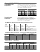
B–2 Specifications Protection Regenerative DC Bus Supply Mode Only 380VAC Input 480VAC Input Bus Overvoltage Trip 670VDC 850VDC Bus Undervoltage Trip 430VDC 520VDC Nominal Bus Voltage 610VDC 735VDC AC Input Overvoltage Trip Factory Set to +15% of Nominal Line Voltage Heatsink Over Temperature Trip 100˚C 1336R Converter Overcurrent Trip Software Overcurrent Limit Hardware Overcurrent Limit Factory Set to 192% of AC Input Current Factory Set to 245% of AC Input Current Line Transients Up to
Specifications B–3 Heat Dissipation Regenerative DC Bus Supply Operation Only — 380-480VAC Input 1336 REGEN Package Amp Rating Converter Converter Heatsink Precharge Unit 10% Line Reactor Power Line Filter Package Total 48A 141W 820W 15W 186W 173W 1335W 78A 193W 1110W 29W 258W 236W 1826W 180A 522W 2664W 58W 474W 317W 4035W Regenerative Brake Operation Only — 380-480VAC Input 1336 REGEN Package Amp Rating Converter Converter Heatsink Precharge Unit 3% Line Reactor Package T
B–4 Specifications Logic Command Structure This information provides the control logic information that is sent to the converter through the logic controllers output image table when the Communication Module is set to control the converter.
Specifications B–5 Serial Communications Module The following fugure shows how the I/O image table for the programmable controller relates to the 1336 REGEN Converter when a Serial Communications Module is used.
B–6 Specifications Remote I/O Communications Module The following fugure shows how the I/O image table for the programmable controller relates to the 1336 REGEN Converter when a Remote I/O Communications Module is used.
Specifications B–7 DeviceNet Communications Module The following fugure shows how the I/O image table for the programmable controller relates to the 1336 REGEN Converter when a Flex I/O Module is used.
B–8 Specifications End of Appendix
Appendix C Spare Parts Information 1336 REGEN Line Regeneration Package Spare Parts Information Current 1336 REGEN Line Regeneration Package spare parts information including recommended parts, catalog numbers and pricing can be obtrained from the following sources: • Allen-Bradley home page on the World Wide Web at: http://www.ab.com then select . . . “Drives” followed by . . . “Product Information” and . . . “Service Information . . .” Select document 1060.
C–2 Spare Parts Information End of Appendix
Index Numbers 120V AC Connection Specifications, 2-14, 3-19 120V AC Current Requirements, 2-12, 3-17 120V AC D Frame Converter Connections, 2-13, 3-18 120V AC Precharge and Converter Wiring, 2-12, 3-17 120V AC Precharge Connections, 2-14, 3-19 1321 Line Reactor, 1-1, 1-4 1336 REGEN Frame Designations, 1-4 1336 REGEN Line Regeneration Package, 1-1 1336 REGEN Line Regeneration Package Components, 1-1 1336 REGEN Operating Mode Application, 1-3 380-480V AC Power Connection Specifications, 2-11, 3-16 380-480V A
I–4 Index determining the rated motor torque (Regenerative Brake Operation), 3-4 Contactor Out - Fault Code No. 10, 4-3 determining the required % of braking torque (Regenerative Brake Operation), 3-5 Diff Drv Type - Fault Code No. 33, 4-4 determining the required braking torque (Regenerative Brake Operation), 3-4 EE Checksum - Fault Code No. 39, 4-5 determining the total inertia (Regenerative Brake Operation), 3-4 Excess Cur Offst - Fault Code No.
Index Sys. Mode Change - Fault Code No. 50, 4-6 Unknown Error - Fault Code No.
I–6 Index Instantaneous Overcurrent Trip Filter Constant - Par. No. 11 - Regen Brake Operation Only, 3-36 Instantaneous Overcurrent Trip Level - Par. No. 14, 2-31, 3-36 Integral Gain - Par. No. 8 - Regen DC Bus Supply Operation Only, 2-30 Logic Status - Par. No. 26, 2-34, 3-39 Motoring Current Limit - Par. No.
Publication 1336 REGEN-5.0 — August, 1999 Supersedes June, 1998 P/N 164968 (04) Copyright 1999 Rockwell International Corporation.