
User Manual - Firmware 1.xxx-6.xxx Instruction Manual


Installation/Wiring 2–41
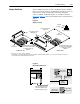
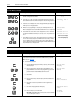
Adapter Definitions Serial communication devices such as the Human Interface Module
that are connected to the drive are identified by SCANport serial com-
munications as Adapters. Depending on the drive and options
ordered, a number of different adapters are available as shown in
Figure 2.8
. Figure 2.9 shows the maximum distance allowed between
devices.
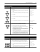
Figure 2.8
Adapter Locations
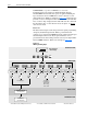
Figure 2.9
Remote Device Distances
Frames
1
A1 - A4
Frames
1
B - G
Main
Control Board
Main
Control Board
Control Interface Option
(TB3 Adapter 0)
Drive Mounted Snap-In HIM,
Internal Communications Module
or Flash Interface Board
(Adapter 1)
Drive Mounted Snap-In HIM,
Internal Communications Module
or Flash Interface Board
(Adapter 1)
Expansion Options
2
Internal Communication
(Adapter 6)
1203-SG2
1203-SG4
Refer to page 1–1 for frame reference classifications.
Communications Port for remote HIM/communication options (Adapter 2) or Expansion Options (Adapters 2, 3, 4, 5) is located on the bottom of the enclosure
(bottom of Main Control Board Mounting Plate for frames F-G).
1
2
2345
23
JOG
ESC
SEL
JOG
ESC
SEL
JOG
ESC SEL
Total cable distance between
each device and drive must
be 10 meters (33 feet) or less.
HIM or Other
Remote Device
JOG
ESC SEL
Length = X Meters
Cable Length in
Meters = 10 – X
Cable Length in
Meters = 10 – X
Adapter 2
Port Expansion
Option
(1203-SG2)
Maximum Cable
Length = 10 Meters
or
HIM or Other
Remote Device
JOG
ESC SEL
120/240V AC
Input
Communication Module
RIO
SCANport
Comm
Status