
User Manual - Firmware 1.xxx-6.xxx Instruction Manual

2–36 Installation/Wiring
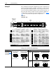
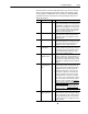
Specifications for the various inputs and outputs are provided below.
1
Use TB2-5 for shield connection.
2
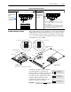
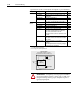
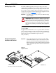
Refer to Typical Isolation diagram below.
I/O Type Configuration Specification Ref.
Standard 0-10V Input 100k ohm input impedance. TB2-4
1
0-10V Output Can drive a 10k ohm load (60 mA short circuit
current limit).
TB2-9
1
0-20 mA Input 200 ohm input impedance. TB2-4
1
10k Ohm Pot. Input 760k ohm input impedance.
Pot. source = 5V through 2.67k ohms to TB2-1.
TB2-4
1
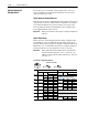
Option
Board
2
0-10V Input 100k ohm input impedance. TB2-5
0-10V Output Can drive 3.3k ohms (3 - parallel 10k ohm loads). TB2-5
0-20 mA Input 100 ohm input impedance. TB2-5
0-20 mA Output Can drive 400 ohms (3 - series 0-20 mA inputs). TB2-5
Pulse Input 250 ohms in series with an opto LED.
Pulse high is greater than 8 mA or 3.6V, while
pulse low is less than 0.8V or 0.2 mA.
Absolute maximum continuous input level is 12V
or 50 mA.
TB2-9
Pulse Output Provides a current limited 4.5V square wave.
This output can drive one PLUS or three PLUS II
pulse inputs.
TB2-5
Thermistor Input 5V across 3.3k ohms in series with the
thermistor.
This arrangement limits the measuring voltage to
less than 2.5V (no self-heating).
TB2-4
!
ATTENTION: Configuring an analog input for 0-20mA
operation and driving it from a voltage source could cause
component damage. Verify proper configuration prior to
applying input signals.
Signal
Conditioning
Signal
Option Board
User
I/O
Power
Typical Isolation
True Galvanic Isolation to 200V
AC
(greater than 10 M ohm, less than 50 pf).