
User Manual - Firmware 1.xxx-6.xxx Instruction Manual

Installation/Wiring 2–31
Pulse Input/Output Option Pulse Input
The pulse input signal must be an externally powered square-wave
pulse at a 5V TTL logic level. As measured at the terminal block,
circuits in the high state must generate a voltage between 3.6 and
5.5V DC at 8 mA. Circuits in the low state must generate a voltage
between 0.0 and 0.8V DC. Maximum input frequency is 250kHz.
Scale factor [Pulse/Enc Scale] must be set.
Pulse Output
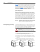
Provides a TTL pulse train suitable for driving up to three
1336
PLUS II pulse inputs or a separate 125 ohm load at TTL levels
(4V at 32 mA source, 0.8V at 3.2 mA sink).
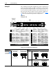
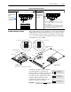
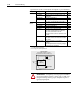
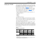
Digital Outputs The digital outputs are at terminals 10 through 18 of TB2.
Figure 2.5
Digital Outputs – TB2
!
ATTENTION: If input voltages are maintained at levels
above ±12V DC, signals may be degraded and component
damage may result.
Only Present
on B Frame
& Up Drives
Reserved for
Future Use
CR2
CR1 CR3CR3 CR4CR4
10
11 12 13 14 15 16 17 18 A1 A2
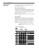
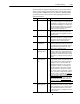
Terminal
TE
10, 11
11, 12
13, 14
14, 15
16, 17
17, 18
A1, A2
Signal
True Earth - Shield Termination
CR1 Programmable Contact
CR2 Programmable Contact
CR3 Programmable Contact
CR4 Programmable Contact
Reserved for Future Use
Resistive Rating = 115V AC/30V DC, 5.0A
Inductive Rating = 115V AC/30V DC, 2.0A
Important: On A Frame drives, the power supply used for relay contact outputs
requires a field installation at the supply source of transient voltage surge
suppression with maximum clamping voltage of 2.5 kV.
Any relay programmed as Fault or Alarm will energize (pick up) when power is applied
to drive and deenergize (drop out) when a fault or alarm exists. Relays selected for
other functions will energize only when that condition exists and will deenergize when
condition is removed.