
User Manual - Firmware 1.xxx-6.xxx Instruction Manual

2–30 Installation/Wiring
Encoder Inputs Encoders must be line driver type, quadrature (dual channel) or pulse
(single channel), 5VDC or 8-15VDC output, single-ended or differ-
ential and capable of supplying a minimum of 10mA per channel.
Maximum input frequency is 250 kHz.
Encoder inputs are available at TB3. The interface board is jumper
selectable to accept a 5V TTL or 12V DC square-wave with a
minimum high state voltage of 3.0V DC (TTL) or 7.0V DC (12 volt
encoder). Maximum high state voltage is 18.5V DC (board damage
could result if voltage is exceeded). Maximum low state voltage is
0.4V DC. See Encoder & Communications Cabling on page 2–11
.
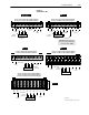
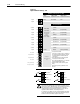
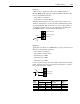
Figure 2.4a
Encoder Signal Wiring
Important: Correct direction of motor rotation as determined during
start-up (see Chapter 5) may require that the A or
B
channel wiring be reversed.
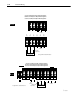
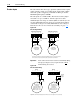
Figure 2.4b
Encoder Power Wiring
31
Single-Ended, Dual-Channel
1
Differential, Dual Channel
1
Single-Ended
Encoder Output
Connections
Differential
Encoder Output
Connections
32 33 34 35 36
A
B NOT
A NOT
B
31
TB3
32 33 34 35 36
to TE
A
B NOT
A NOT
B
TB3
to TE
to
Power Supply Common
(Terminal 36 or External)
1
For Single-Channel applications, eliminate the B and B (NOT) connections. Some encoders may label
the "A" connection as "Signal." Single-channel provides speed indication Only, Not direction.
Common
+12V DC
(200 mA)
31
TB3
to TE
Internal External
Encoder Power
Connections
using 12V DC Internal
(Drive) Power Source
Encoder Power
Connections using
External DC
Power Source
32 33 34 35 36
+
Common
External
Power
Supply
31
TB3
32 33 34 35 36
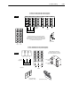
Important: Control Interface Board jumpers JP3 & JP4 must be set for the voltage level of the encoder output.
Minimum On Volts = 7V DC
Minimum Current = 10mA
Minimum On Volts = 3V DC
Minimum Current = 10mA
to TE