
User Manual - Firmware 1.xxx-6.xxx Instruction Manual

A–12 Specifications and Supplemental Information
To allow convenient control of the Traverse and Sync functions through
SCANport adapters, an alternate definition of the SCANport type 2
command can be selected. See also [Alt Type 2 Cmd].
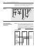
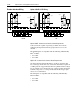
Typical Programmable
Controller Communications
Configurations
Important: If block transfers are programmed to continuously write
data to the drive, the EEPROM will quickly exceed its life
cycle and malfunction. The 1336 PLUS
II does not use
RAM to temporarily store parameter data, but rather stores
the data immediately to the EEPROM. Since the EEPROM
has a defined number of “write” cycles available,
continuous
block transfers should not be programmed.
Using Datalink A
1
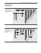
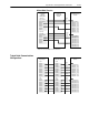
Alternate Logic Control
Structure
Bit 15 Bit 13 Bit 12 Bit 11 Bit 10 Bit 9 Bit 8 Bit 7 Bit 6 Bit 5 Bit 4 Bit 3 Bit 2 Bit 1 Bit 0Bit 14
Direction 5 4
No Command 0 0
Forward 0 1
Reverse 1 0
Hold Direction 1 1
Time 9/11 8/10
No Command 0 0
Time 1 0 1
Time 2 1 0
Hold Time 1 1
Reference 14 13 12
No Command 0 0 0
Freq Select 1 0 0 1
Freq Select 2 0 1 0
Preset Freq 3 0 1 1
Preset Freq 4 1 0 0
Preset Freq 5 1 0 1
Preset Freq 6 1 1 0
Preset Freq 7 1 1 1
Start
1 = Start
0 = Not Start
Stop
1 = Stop
0 = Not Stop
Jog
1 = Jog
0 = Not Jog
Clear Faults
1 = Clear Faults
0 = Not Clear Faults
Local
1 = Local Lockout
0 = Not Local
Sync Enable
1 = Enabled
0 = Not Enabled
Traverse Enable
1 = Enabled
0 = Not Enabled
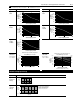
Reference Select Decel Time Accel Time
Programmable
Controller
I/O Image Table
Remote I/O
Communication
Module
Adjustable Frequency
AC Drive
Block Transfer
Logic Command
Analog Reference
WORD 3
WORD 4
WORD 5
WORD 6
WORD 7
Output Image
Data In A1
Data In A2
Data Out A1
Data Out A2
111
112
119
120
Parameter/Number
Block Transfer
Logic Status
Analog Feedback
WORD 3
WORD 4
WORD 5
WORD 6
WORD 7
Input Image
Datalink A
Datalink A