
User Manual - Firmware 1.xxx-6.xxx Instruction Manual

6–58 Programming
Motor Control
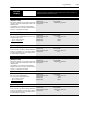
[IR Drop Volts]
Used in “Economize” & “Sens Vector” modes - Sets the
value of volts dropped across the resistance of the motor
stator. If set to zero, the drive will use an internal value
based on motor F.L.A. and rated voltage. Some motors
(i.e. 6 pole, special, etc.) may be particularly sensitive to
the adjustment of this parameter. Refer to the tuning pro-
cedure in Chapter 5 for further information.
Parameter Number 194
Parameter Type Read and Write
Display Units / Drive Units 0.1 Volt / 4096 = Drive Rated Volts
Factory Default Based on Drive Size & Type
Minimum Value 0.0 Volts
Maximum Value 25% of Drive Rated Volts
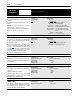
[Flux Up Time]
Sets the amount of time the drive will use to try and achieve
full motor stator flux. When a Start command is issued, DC
current at current limit level is used to build stator flux be-
fore accelerating.
Parameter Number 200
Parameter Type Read and Write
Display Units / Drive Units 0.1 Sec / Sec x 10
Factory Default 0.0 Sec
Minimum Value 0.0 Sec
Maximum Value 5.0 Sec
[Start Boost]
This parameter sets the DC start boost level for accelera-
tion when [Control Select] is set to “Fixed Boost” or “Full
Custom.”
Parameter Number 48
Parameter Type Read and Write
Display Units / Drive Units 1 Volt / 4096 = Drive Rtd Volts
Factory Default 0 Volts
Minimum Value 0 Volts
Maximum Value 9.5% of Drive Rated Voltage
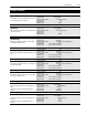
[Run Boost]
This parameter sets the DC boost level for constant speed
level when [Control Select] is set to “Fixed Boost” or “Full
Custom.”
Parameter Number 83
Parameter Type Read and Write
Display Units / Drive Units 1 Volt / 4096 = Drive Rtd Volts
Factory Default 0 Volts
Minimum Value 0 Volts
Maximum Value 9.5% of Drive Rated Voltage
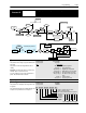
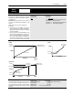
[Boost Slope]
Sets the slope of the volts/Hertz curve from [Start Boost]
and [Run Boost] to the intersect point (see Fixed boost
diagram on previous page) when [Control Select] equals
fixed boost. The intersect is determined by multiplying:
Run Boost x Boost Slope = A
Start Boost x Boost Slope = B.
Parameter Number 169
Parameter Type Read and Write
Display Units / Drive Units None
Factory Default 1.5
Minimum Value 1.0
Maximum Value 8.0
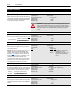
[Break Voltage]
Sets the voltage the drive will output at [Break Frequency].
Combined with [Break Frequency], this parameter deter-
mines the volts-per-Hertz pattern between 0 and [Break
Frequency].
Parameter Number 50
Parameter Type Read and Write
Display Units / Drive Units 1 Volt / 4096 = Drive Rtd Volts
Factory Default 25% of Drive Rated Voltage
Minimum Value 0 Volts
Maximum Value 50% of Drive Rated Voltage
[Break Frequency]
This parameter sets a midpoint frequency on a custom
volts-per-Hertz curve. Combined with [Break Voltage], this
value determines the volts-per-Hertz ratio between 0 and
[Break Frequency].
Parameter Number 49
Parameter Type Read and Write
Display Units / Drive Units 1 Hertz / Hertz x 10
Factory Default 25% of [Maximum Freq]
Minimum Value 0 Hz
Maximum Value 120 Hz
[Base Voltage]
This value should be set to the motor nameplate rated
voltage.
Parameter Number 18
Parameter Type Read and Write
Display Units / Drive Units 1 Volt / 4096 = Drive Rtd Volts
Factory Default Drive Rated Volts
Minimum Value 25% of Drive Rated Voltage
Maximum Value 120% of Drive Rated Voltage