
User Manual - Firmware 1.xxx-6.xxx Instruction Manual

Programming 6–53
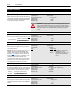
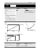
Process PI
This group of parameters configures the Process PI Regulator.
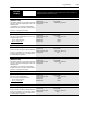
[Speed Control]
This parameter selects the type of speed modulation active
in the drive.
This parameter cannot be changed while the drive is
running.
Important: “No Control” and “Phase Lock” are the only
available options for synchronous motors.
If encoder feedback closed loop speed regulation is re-
quired, “Encoder Fdbk” must be selected.
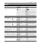
Parameter Number 77
Parameter Type Read and Write
Factory Default “Slip Comp”
Units
Display Drive
“No Control” 0 Frequency regulation
“Slip Comp” 1 Slip compensation
“Speed Droop” 2 Negative slip compensation
“Phase Lock” 3 Enable phase lock to pulse input
“Encoder Fdbk” 4 Encoder feedback-closed loop
“Droop + Reg” 5 Enc. fdbk.-closed loop w/ active
droop
“P Jump” 6 Traverse function
“Process PI” 7 Closed loop PI control
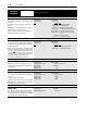
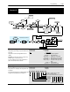
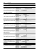
[PI Config]
This parameter sets and displays the configuration for the
PI regulator.
Note: Reset Integrator (Int) is also available through a dig-
ital input. See Input Mode Selection in Chapter 2.
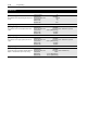
Parameter Number 213
Parameter Type Read/Write
Factory Default 00000000
PI Reference
PI Reference
Select
pi reference
∑
∑
√
PI Config.sqrt_fdbk
PI Config.inv_error
PI Config.reset_int
PI Feedback
Freq Command
PI Error
Master Frequency Reference
Process KI
s
Process KP
Integral Term = 0
PI + Clamp
PI – Clamp
PI Output
Speed
Adder
Output Frequency
Speed
Command
Speed
Ramp
pi feedback
PI Feedback
Select
Compute
Speed
Accel
Control
+
–1
–
+
+
∑
PI Config.zero_clamp
speed ramp>0
+
+
PI Enable
+32767
Parameter 65
–32767
–32767
+32767
0
0
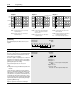
Bit 7 Bit 6 Bit 5 Bit 4 Bit 3 Bit 2 Bit 1 Bit 0
Inv Error - Changes sign of PI Error
Reset Int - Holds KI at zero
Zero Clamp - Prevents bidirectional operation
Sqrt Fdbk - Uses sq. root of PI feedback value
Set Output 000011
Preload Int 001100
PI Enable 010101
Diagram 1 2 3
(Refer to Diagrams on next page)
Spare