
User Manual - Firmware 1.xxx-6.xxx Instruction Manual

6–50 Programming
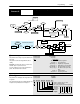
Encoder
Feedback
This group of parameters contains all the parameters necessary to activate encoder feed-
back for closed loop operation.
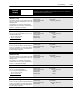
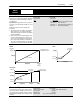
[Speed Control]
This parameter selects the type of speed modulation active
in the drive.
This parameter cannot be changed while the drive is
running.
Important: “No Control” and “Phase Lock” are the only
available options for synchronous motors.
If encoder feedback closed loop speed regulation is re-
quired, “Encoder Fdbk” must be selected.
Parameter Number 77
Parameter Type Read and Write
Factory Default “Slip Comp”
Units
Display Drive
“No Control” 0 Frequency regulation
“Slip Comp” 1 Slip compensation
“Speed Droop” 2 Negative slip compensation
“Phase Lock” 3 Enable phase lock to pulse input
“Encoder Fdbk” 4 Encoder feedback-closed loop
“Droop + Reg” 5 Enc. fdbk.-closed loop w/ active
droop
“P Jump” 6 Traverse function
“Process PI” 7 Closed loop PI control
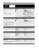
[Encoder Type]
This parameter selects the feedback encoder signal type.
The drive can accept single channel (Pulse) or dual chan-
nel (Quadrature) signals.
This selection must match the type of encoder being used.
If “Pulse” is selected and a dual channel encoder is wired
(see page 2–30
), the feedback indication will be incorrect
by a factor of 2 and no direction indication will be offered.
If “Quadrature” is selected and a single channel encoder
is wired, the feedback value will always be zero.
This cannot be changed while drive is running.
Parameter Number 152
Parameter Type Read and Write
Factory Default “Quadrature”
Units
Display Drive
“Pulse” 0 Single channel encoder
“Quadrature” 1 Dual channel encoder
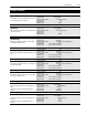
[Encoder PPR]
This parameter contains the scaling factor for encoder
feedback speed regulation. Enter the actual encoder puls-
es per revolution
Parameter Number 46
Parameter Type Read and Write
Display Units / Drive Units Factor / Pulses per Rev
Factory Default 1024 PPR
Minimum Value 1
Maximum Value 4096
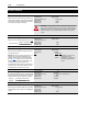
[Maximum Speed]
This Parameter sets the output frequency at full frequency
reference for:
1.Encoder feedback speed regulation.
2.All analog inputs to TB2 (remote pot, 0-10V & 0-20 mA).
NOTE: [Maximum Freq.] must be raised to allow operation
or modulation above [Maximum Speed].
Parameter Number 151
Parameter Type Read and Write
Display Units / Drive Units 1 Hertz / Hertz x 10
Factory Default 400 Hz
Minimum Value 0 Hz
Maximum Value 400 Hz
[Motor Poles]
This parameter contains the number of motor magnetic
poles. This value translates output frequency into actual
motor RPM during closed loop operation. It is calculated
from [Motor NP Hertz] and [Motor NP RPM].
Parameter Number 153
Parameter Type Read Only
Display Units / Drive Units 1 Poles / Poles