
User Manual - Firmware 1.xxx-6.xxx Instruction Manual

6–48 Programming
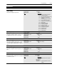
Adapter I/O
This group of parameters contains the parameters needed for an optional communications
adapter to communicate with the drive.
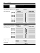
These parameters determine the parameter number to
which PLC output data table or SCANport device image
information will be written. Refer to the A-B Single Point
Remote I/O Adapter manuals or other SCANport device
manual for data link information.
Parameter Number 111-118
Parameter Type Read and Write
Display Units / Drive Units Parameter # / Parameter #
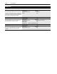
These parameters determine the parameter number
whose value will be read into the PLC input data table or
SCANport device image. Refer to the A-B Single Point Re-
mote I/O Adapter manuals or other SCANport device
manual for data link information.
Parameter Number 119-126
Parameter Type Read and Write
Display Units / Drive Units Parameter # / Parameter #
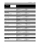
[Alt Type 2 Cmd]
When ENABLED, alternate functions are assigned to
some bits in the Logic Control Structure. See Appendix A
for further information.
Parameter Number 315
Parameter Type Read and Write
Factory Default “Disabled”
Units
Display Drive
“Disabled” 0
“Enabled” 1
[Data In A1]
[Data In A2]
[Data In B1]
[Data In B2]
[Data In C1]
[Data In C2]
[Data In D1]
[Data In D2]
1336 PLUS II SCANport Device
[Data Out A1]
[Data Out A2]
[Data Out B1]
[Data Out B2]
[Data Out C1]
[Data Out C2]
[Data Out D1]
[Data Out D2]
1336 PLUS II SCANport Device