
User Manual - Firmware 1.xxx-6.xxx Instruction Manual

6–36 Programming
Diagnostics
This group of parameters contains values that can be helpful in explaining the operation of
the drive. Drive status, direction, control and alarm conditions as well as drive ratings are
included.
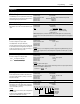
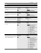
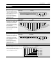
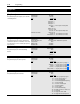
[Drive Status 1]
This parameter displays the actual oper-
ating condition in binary format.
Bits 0-7 are displayed on lower half of
line 2 on HIM display, while, bits 8-15 are
displayed on the upper half of line 2.
A Status description (bit ENUM) is dis-
played on line 1 (except Series A HIMs
below version 3.0).
Parameter Number 59
Parameter Type Read Only
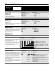
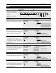
[Drive Status 2]
This parameter displays the actual operating con-
dition in binary format.
Bits 0-7 are displayed on lower half of line 2 on HIM
display, while, bits 8-15 are displayed on the upper
half of line 2.
A Status description (bit ENUM) is displayed on line
1 (except Series A HIMs below version 3.0).
Parameter Number 236
Parameter Type Read Only
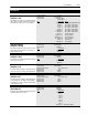
[Application Sts]
Displays status of Speed Sync and Traverse functions.
Parameter Number 316
Parameter Type Read Only
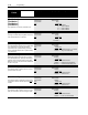
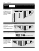
[Drive Alarm 1]
This parameter displays which alarm
condition is present when bit 6 of [Drive
Status 1] is high (set to 1). Refer to Chap-
ter 7 for further alarm information.
A Status description (bit ENUM) is dis-
played on line 1 (except Series A HIMs
below version 3.0).
Parameter Number 60
Parameter Type Read Only
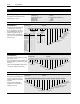
Enabled
Running
Command Direction
Actual Direction
Accelerating
Decelerating
Faulted
At Speed
Bit 15 Bit 13 Bit 12 Bit 11 Bit 10 Bit 9 Bit 8 Bit 7 Bit 6 Bit 5 Bit 4 Bit 3 Bit 2 Bit 1 Bit 0
Alarm
0 = Reverse
1 = Forward
0 = Reverse
1 = Forward
Reference
ID
Local
Adapter ID
Reference 15 14 13 12
Freq Select 10000
Preset Freq 1 0 0 0 1
Preset Freq 2 0 0 1 0
Preset Freq 3 0 0 1 1
Preset Freq 4 0 1 0 0
Preset Freq 5 0 1 0 1
Preset Freq 6 0 1 1 0
Preset Freq 7 0 1 1 1
Freq Select 21000
Adapter 1 1 0 0 1
Adapter 2 1 0 1 0
Adapter 3 1 0 1 1
Adapter 4 1 1 0 0
Adapter 5 1 1 0 1
Adapter 6 1 1 1 0
Jog Frequency 1 1 1 1
Local 11 10 9
TB3 0 0 0
1001
2010
3011
4100
5101
6110
Unused 1 1 1
Bit 14
At Freq
At Current
At Torque
Current Lmt
Mtr Overload
Line Loss
Drive Ready
Forward Run
Bit 15 Bit 13 Bit 12 Bit 11 Bit 10 Bit 9 Bit 8 Bit 7 Bit 6 Bit 5 Bit 4 Bit 3 Bit 2 Bit 1 Bit 0
Drive Power
Bit 14
Reverse Run
Braking
Auto Reset
Economize
At Temp
PI Max Error
Startup
Bit 7 Bit 5 Bit 4 Bit 3 Bit 2 Bit 1 Bit 0
Speed Sync – 0 = Disabled, 1 = Enabled
Traverse – 0 = Disabled, 1 = Enabled
Not Used
Bit 6
Bus Charging
Regenerating Current Limit
Regenerating Voltage Limit
Line Loss In Progress
Motor StalledGround Warning
Bit 15 Bit 13 Bit 12 Bit 11 Bit 10 Bit 9 Bit 8 Bit 7 Bit 6 Bit 5 Bit 4 Bit 3 Bit 2 Bit 1 Bit 0
Mtr Overload
Sync Loss
Bit 14
Hardware Current Limit
Motoring Current Limit
Motor OL Trip
Auto Reset
Phase Loss
Heatsink Temp
Auxiliary Input
4-20 mA Loss