
User Manual - Firmware 1.xxx-6.xxx Instruction Manual

Programming 6–35
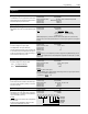
Faults
[Fault Alarms 2]
This parameter stores and displays the
last alarm conditions present prior to a
fault. Refer to Chapter 7 for further alarm
information.
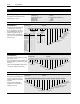
A Status description (bit ENUM) is
displayed on line 1 (except Series A
HIMs below version 3.0).
Parameter Number 287
Parameter Type Read Only
[Flt Clear Mode]
This parameter controls the method for clearing faults.
Parameter Number 39
Parameter Type Read and Write
Factory Default “Enabled”
Units
Display Drive
“Disabled” 0 Faults cleared only by cycling power
“Enabled” 1 Faults cleared by issuing a valid stop
command (only through TB3/HIM) or
cycling power - see Bit 3 of the Logic
Control Structure in Appendix A.
[Ground Warning]
Enables the Ground Warning fault (F57) when the drive
senses ground current in excess of 2 amperes (approxi-
mate). Refer to Chapter 7 for further information.
Parameter Number 204
Parameter Type Read and Write
Factory Default “Disabled”
Units
Display Drive
“Disabled” 0 No Fault Generated
“Enabled” 1 Ground Warning Generated
[Phase Loss Mode]
Enables the function that detects a phase loss or the
current rating has been exceeded in the drive if powered
on single-phase line. A fault (F49) or alarm condition will
occur if the DC bus ripple voltage exceeds the level in
[Phase Loss Level].
Parameter Number 330
Parameter Type Read and Write
Factory Default “Disabled”
Units
Display Drive
“Disabled” 0 No Fault Generated
“Alarm” 1 Generates a Phase Loss Alarm
“Fault” 2 Generated F49 Input Phase Fault
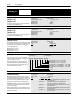
[Phase Loss Level]
Sets the DC bus ripple voltage above which a phase loss
fault/alarm will occur. The sensitivity for detecting a blown
fuse on a three-phase system can be increased by
lowering the setting for this parameter.
Parameter Number 331
Parameter Type Read and Write
Display Units / Drive Units 0.1 Volts / 4096 = Drive Rtd Volts
Factory Default 9.0/18.0/22.5 Volts
12.4/24.7/30.9 Volts Firmware 6.001 & later
Minimum Value 5.1/10.1/12.7 Volts
Maximum Value 22.5/45.0/56.2 Volts
45.0/90.0/112.5 Volts Firmware 6.001 & later
[Precharge Fault]
Enables or disables the Precharge Fault, which indicates
insufficient DC bus charging 20 seconds after power-up.
Parameter Number 332
Parameter Type Read and Write
Factory Default “Enabled”
Units
Display Drive
“Disabled” 0 No Fault Generated
“Enabled” 1 Precharge Fault Generated
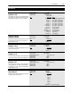
[Motor OL Ret] – Firmware 6.001 & later
When enabled, the accumulated motor overload count will
be stored on power-down and restored on power-up. From
that point, normal overload operation continues. When the
value is changed from enabled to disabled the motor
overload count will be reset to 0.
Parameter Number 379
Parameter Type Read and Write
Factory Default “Disabled”
Units
Display Drive
“Disabled” 0 Motor OL count not saved
“Enabled” 1 Motor OL count saved on power-
down and restored on power-up
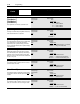
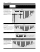
Motor Therm
Bit 15 Bit 13 Bit 12 Bit 11 Bit 10 Bit 9 Bit 8 Bit 7 Bit 6 Bit 5 Bit 4 Bit 3 Bit 2 Bit 1 Bit 0Bit 14
Unused
Encoder Loss
Load Loss
Enc Cnt Max
Enc Cnt Set
Voltage Check