
User Manual - Firmware 1.xxx-6.xxx Instruction Manual

6–30 Programming
Analog I/O
This group of parameters contains the programming options for analog drive inputs/outputs.
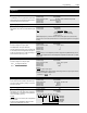
[Anlg In 0 Lo]
[Anlg In 1 Lo]
[Anlg In 2 Lo]
Sets the percentage of voltage or current from Input 0, 1
or 2 that represents [Minimum Freq].
Parameter Number 237, 239, 248
Parameter Type Read and Write
Display Units / Drive Units 0.1% / 920 = 100%
Factory Default 0.0%
Minimum Value – 300.0%
Maximum Value +300.0 %
[Anlg In 0 Hi]
[Anlg In 1 Hi]
[Anlg In 2 Hi]
Sets the percentage of voltage or current from Input 0, 1
or 2 that represents [Maximum Freq].
Parameter Number 238, 240, 249
Parameter Type Read and Write
Display Units / Drive Units 0.1% / 920 = 100%
Factory Default 100.0 %
Minimum Value – 300.0%
Maximum Value +300.0 %
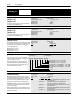
[Analog Trim En]
This parameter enables Analog In 0 as a trim input. Setting
this parameter to “Enable” creates a trim signal to the ac-
tive frequency source at Analog In 0. The trim value is
±10% of [Maximum Freq].
Minimum Input = –10% Trim
Mid-Point Input = No Trim
Maximum Input = +10% Trim
Parameter Number 90
Parameter Type Read and Write
Factory Default “Disabled”
Units
Display Drive
“Disabled” 0
“Enabled” 1
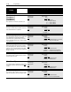
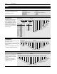
[Anlg Signal Loss]
Selects the drive reaction to a loss of analog input
signal. This signal could represent commanded fre-
quency, PI feedback, or others.
Bits 0-2 define the input as a pot with wiper loss
detect and will generate an “Open Pot Fault” (F09).
Bits 3-5 define the input as offset (4mA, 2V) with loss
detect below that value (see below).
Parameter Number 250
Parameter Type Read and Write
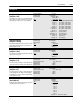
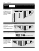
[4-20mA Loss Sel]
This parameter selects the drives response to a loss of
analog input signal (input below 2V or 4mA). Requires that
the loss selection bits for [Anlg Signal Loss] be set to “1.”
This function is active only when the input is configured
in [Freq Select 1/2], [PI Ref Select], [PI Fdbk Select].
Important: Depending on the type of input configuration
(i.e. Frequency or PI), the resultant action will vary (see
“Action” column at right).
When configured in [PI Ref Select] or [PI Fdbk Select], only
the alarm and fault conditions will occur. The drive will not
perform a speed change.
Parameter Number 150
Parameter Type Read and Write
Factory Default “Min/Alarm”
Units
Display Drive Action
“Min/Alarm” 0 Freq - Drive outputs [Minimum Freq] and issues an alarm.
PI - Alarm issued.
“Stop/Fault” 1 Freq - Drive stops and issues “Hertz Err Fault”.
PI - Drive stops and issues “Hertz Err Fault”.
“Hold/Alarm” 2 Freq - Drive maintains last output freq & issues an alarm.
PI - Alarm issued.
“Max/Alarm” 3 Freq - Drive outputs [Maximum Freq] and issues an alarm.
PI - Alarm issued.
“Pre1/Alarm” 4 Freq - Drive outputs [Preset Freq 1] and issues an alarm.
PI - Alarm issued.
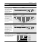
Bit 7 Bit 6 Bit 5 Bit 4 Bit 3 Bit 2 Bit 1 Bit 0
Input 0 Signal Loss for Pot – 1=Yes, 0=No
Input 1 Signal Loss for Pot – 1=Yes, 0=No
Input 2 Signal Loss for Pot – 1=Yes, 0=No
Input 0 Signal Loss for 4-20mA/2-10V – 1=Yes, 0=No
Input 1 Signal Loss for 4-20mA/2-10V – 1=Yes, 0=No
Input 2 Signal Loss for 4-20mA/2-10V – 1=Yes, 0=No
Not Used
Not Used