
User Manual - Firmware 1.xxx-6.xxx Instruction Manual

Programming 6–29
Digital I/O
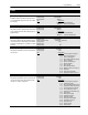
[PI Max Error]
Used with the process PI loop and sets the PI error value
which activates CR1-4 (if selected).The relay(s) will be ac-
tivated when [PI Error] exceeds this value.
Parameter Number 293
Parameter Type Read and Write
Display Units / Drive Units 0.01 Hertz / 32767 = Maximum Freq Forward
Factory Default Maximum Freq Forward
Minimum Value –400.00 Hz
Maximum Value 400.00 Hz
[Pulse Out Select]
This parameter selects the source value that drives pulse
output.
Parameter Number 280
Parameter Type Read and Write
Factory Default “Output Freq”
Units
Display Drive Range
“Output Freq” 0 See [Output Freq]
“Encoder Freq” 1 See [Encoder Freq]
“Acc/Dec Freq” 2
NOTE: Output frequency command of the drive directly at the output of the accel/decel ramp
generator. It does not include any modification due to selected speed regulation mode via [Speed
Control].
[Pulse Out Scale]
Provides a scaling factor for pulse output.
Pulse Output Rate = Hz x [Pulse Out Scale]
The pulse output will not provide a rate lower than 21 Hz.
A command less than 21 Hz will generate 0 Hz output. To
provide smooth operation across a wide speed range, se-
lect the maximum scale factor possible.
Parameter Number 281
Parameter Type Read and Write
Display Units / Drive Units Factor / Factor
Factory Default 1
Minimum Value 1
Maximum Value 64
Example
:
[Pulse Out Select] is set to “Output Freq” and drive is programmed for [Maximum Freq] = 60 Hz.
When the drive output is 60 Hz, the Pulse Output Rate is adjustable from 60 Hz (60 x 1) to 3840
Hz (60 x 64).
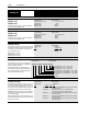
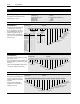
[Pulse In Scale]
Provides a scaling factor for the pulse input.
Parameter Number 264
Parameter Type Read and Write
Display Units / Drive Units Factor / Pulses per Rev
Factory Default 64 PPR
Minimum Value 1
Maximum Value 4096
Example
:
4 Pole Motor, 60 Hz = Max. Speed.
The 1336-MOD-N1 option outputs 64 Hz/Hz. At full analog reference, the pulse input to the drive
will be 60 Hz x 64 Hz/Hz = 3840 pulses/sec.
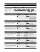
[At Time]
Sets the delay time for the activation of the CR1-4 relays.
The relay is activated at Start + [At Time] seconds. This
delay affects all relays.
Parameter Number 327
Parameter Type Read and Write
Display Units / Units 0.01 Second / Seconds x 100
Factory Default 0.00 Sec
Minimum Value 0.00 Sec
Maximum Value 360.00 Sec
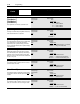
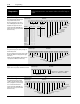
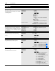
[Remote CR Output]
Individual bits control relay outputs when selected with
[CR1-4 Out Select]. 1 = Energize Coil. This parameter is
reset to the default on power-up.
Example
:
If [CR2 Out Select] is set to “Remote,” bit 1 of this parameter
will control CR2.
A Status description (bit ENUM) is displayed on line 1
(except Series A HIMs below version 3.0).
Parameter Number 326
Parameter Type Read and Write
Factory Default xxxx0000
Scale
Factor
Incoming Pulse Rate (Hz)
Desired Command Freq.
=
Scale Factor =
3840 Hz
60 Hz
= 64
Bit 7 Bit 6 Bit 5 Bit 4 Bit 3 Bit 2 Bit 1 Bit 0
CR1 Output
CR2 Output
CR3 Output
CR4 Output
Not Used