336 IMPACT Quick Start Guide This Quick Start Guide summarizes the basic steps needed to install, start-up, and program the 1336 IMPACT Adjustable Frequency AC Drive. The information provided Does Not replace the User Manual and is intended for qualified drive service personnel only. Refer to the 1336 IMPACT User Manual (publication 1336 IMPACT-5.0) for details on other application considerations and related precautions.
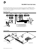
1336 IMPACT Quick Start Guide Wiring I/O – A-Frames J4 (TB4) J7 (TB7) + Analog Input 1 - 1 Com 2 -10V 3 Shield 4 2 Shield Analog Input 2 +10V 1 3 + 4 - 5 Shield Analog Output 1 5 - 6 6 + 7 - 8 Shield Analog Output 2 + 8 - 9 9 + 10 - 11 Shield J10 (TB10) 7 Shield 4 to 20 mA Pulse Source + 1 2 3 4 5 6 7 8 9 10 11 + 11 - 12 4 to 20 mA 12 TE 10 Shield 12 * The power supply is for drive input use only.
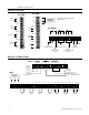
1336 IMPACT Quick Start Guide L Option Board 1 2 3 4 5 6 7 8 9 10 11 12 13 14 15 16 17 18 19 20 21 22 23 24 25 26 27 28 29 30 Status Start Start Start Start Start Start Start Start Start Start Run Fwd Run Fwd Run Fwd Run Fwd Run Fwd Start Start Start Start Start Start Run Fwd Run Fwd Run Fwd Run Fwd Start Start Start Run Fwd Stop/Clr Flt Stop/Clr Flt Stop/Clr Flt Stop/Clr Flt Stop/Clr Flt Stop/Clr Flt Stop/Clr Flt Stop/Clr Flt Stop/Clr Flt Stop/Clr Flt Stop/Clr Flt Stop/Clr Flt Stop/Clr Flt Stop/Clr Flt
1336 IMPACT Quick Start Guide 1. Verify that AC line power and control power match the drive rating. 2. If an L option is installed, verify that the Stop and Enable interlock inputs are present. If this option is not installed, verify that jumpers are installed at pins 3 and 4 and 17 and 18 on J5 on A Frame drives or J2 on B Frame and up drives. Refer to Jumper Locations. 3. If standard I/O is being used, verify that jumpers are wired correctly. 4.
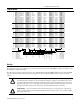
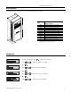
1336 IMPACT Quick Start Guide Drive Dimensions To determine the size of your drive, refer to the following illustration and table. Frame Height A1 A2 A3 A4 B C D E-Enclosed E-Open F G H De pth idth W ➀ Width x Height x Depth Millimeters (inches) 215.9 (8.50) x 290.0 (11.42) x 160.0 (6.30) 215.9 (8.50) x 290.0 (11.42) x 180.5 (7.10) 215.9 (8.50) x 290.0 (11.42) x 207.0 (8.15) 260.0 (10.24) x 350.0 (13.78) x 212.0 (8.35) 276.4 (10.88) x 476.3 (18.75) x 225.0 (8.86) 301.8 (11.88) x 701.0 (27.
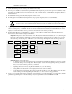
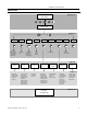
1336 IMPACT Quick Start Guide HIM Structure Power-Up and Status Display or or or Operator Level or Choose Mode Mode Level EEProm Save Values Recall Values Reset Defaults Drive to HIM HIM to Drive Control Status Search Parameters Links Password Control Logic Reset Drive1 Fault Queue Warning Queue Display Login Logout Modify Process Process Display Link Program Start Up Set Links Clear All Links File Level Monitor Control Motor Status Drive/Inv Status SCANport Status Fault Status Test
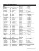
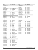
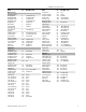
1336 IMPACT Quick Start Guide Parameters - Files, Groups, and Elements Name Monitor Motor Status Motor Speed Motor Frequency Motor Current Motor Voltage Motor Voltage % Motor Torque % Motor Flux % Motor Power% Enc Pos Fdbk Low Enc Pos Fdbk Hi Int Torque Ref Drive/Inv Status DC Bus Voltage Logic Input Sts Drive/Inv Status Drive/Inv Sts 2 Run Inhibit Sts Command Spd Sts Torque Limit Sts Spd Reg Output Spd Error SCANport Status Dir/Ref Owner Start/Stop Owner Jog1/Jog2 Owner Ramp/ClFlt Owner Flux/Trim Owner F
1336 IMPACT Quick Start Guide Name Fault Config cont.
1336 IMPACT Quick Start Guide Name Motor Inverter Motor Nameplate Nameplate HP Nameplate RPM Nameplate Amps Nameplate Volts Namplate Hz Motor Poles Service Factor Encoder Data Encoder PPR Inverter PWM Frequency Inverter Amps Inverter Volts Motor Constants Stator Resistance Leak Inductance Flux Current Slip Gain Motor Poles Application Flux Braking Bus/Brake Option DC Braking/Hold Bus/Brake Option DC Brake Current DC Brake Time 400% Mtr Current Max Mtr Current Fast Flux Up Bus/Brake Option Fast Flux Level S
1336 IMPACT Quick Start Guide This Page Intentionally Blank 10 Publication 1336 IMPACT-5.
1336 IMPACT Kurzanleitung In dieser Kurzanleitung wird beschrieben, wie Sie den Frequenzumrichter 1336 IMPACT installieren, in Betrieb nehmen und programmieren. Die hierin enthaltenen Informationen sind jedoch kein Ersatz für das Benutzerhandbuch und sind nur für qualifiziertes FU-Wartungspersonal vorgesehen. Detaillierte Informationen über andere Anwendungsaspekte und die entsprechenden sicherheitstechnischen Hinweise finden Sie im 1336 IMPACT-Benutzerhandbuch (Publikation 1336 IMPACT-5.0).
1336 IMPACT Kurzanleitung Verdrahtungs-E/A – Baugröße A J4 (TB4) J7 (TB7) + 1 - 2 Abschirmung 3 + 1 +10V Bezugspotential 2 -10V 3 4 Abschirmung 4 - 5 5 Abschirmung 6 + Analogausgang 1 - + 7 Abschirmung 7 - 8 8 Abschirmung 9 + Analogausgang 2 - Analogeingang 2 4 bis 20 mA + 10 - 11 Abschirmung 12 Impulsquelle * Das Netzteil ist nur zur Verwendung für den FU-Eingang vorgesehen.
36 IMPACT Kurzanleitung L-Optionsplatine 1 2 3 4 5 6 7 8 9 10 11 12 13 14 15 16 17 18 19 20 21 22 23 24 25 26 27 28 29 30 Status Start Start Start Start Start Start Start Start Start Start Vorwärts Vorwärts Vorwärts Vorwärts Vorwärts Start Start Start Start Start Start Vorwärts Vorwärts Vorwärts Vorwärts Start Start Start Vorwärts Stop/Alarm Löschen Stop/Alarm Löschen Stop/Alarm Löschen Stop/Alarm Löschen Stop/Alarm Löschen Stop/Alarm Löschen Stop/Alarm Löschen Stop/Alarm Löschen Stop/Alarm Löschen Sto
1336 IMPACT Kurzanleitung 1. Überprüfen Sie, ob die Netzspannung und die Steuerspannung der FU-Nennleistung entsprechen. 2. Falls eine L-Option installiert wurde, überprüfen Sie, ob die Stopp- und Freigabeeingänge vorhanden sind. Wurde diese Options nicht installiert, überprüfen Sie, ob die Brücken bei FUs der Baugröße A an den Stiften 3 und 4 sowie 17 und 18 von J5 bzw. bei FUs der Baugröße B und höher von J2 angebracht wurden. Siehe „Brückenpositionen“. 3.
1336 IMPACT Kurzanleitung 7. Das Gerät aus- und wieder einschalten, um die vorgenommenen Änderungen zu aktivieren. Damit ist das Inbetriebnahmeverfahren beendet. Je nach Anwendung können eine weitere Parameterprogrammierung und/oder eine erweiterte Inbetriebnahme erforderlich sein. Einzelheiten finden Sie im Benutzerhandbuch. FU-Abmessungen Ziehen Sie zur Feststellung der Größe des Frequenzumrichters die folgende Abbildung und Tabelle zu Rate.
1336 IMPACT Kurzanleitung Struktur der Bedieneinheit (HIM) Inbetriebnahmemodus und Statusanzeige oder oder oder Bedienerebene oder Modus wählen Modusebene EEProm Werte speichern Werte aufrufen Std. wert rücks.
1336 IMPACT Kurzanleitung Parameter – Dateien, Gruppen und Elemente Bezeichnung Nr. Monitor Motorstatus Motordrehzahl 81 Motorfrequenz 89 Strom Motor 83 Motorspannung 85 Motorspannung % 234 Motordrehmom. % 86 Motorfluß % 88 Motor Leistung % 90 Enc.Pos.Mldg. niedr 227 Enc.Pos.Mldg. hoch 228 Int. Drehmomentref. 229 Status Antrieb/Wechselrichter Spanng.GS-Bus 84 Stat.Log.Eingabe 14 Stat.Antr/Wchslr 15 Stat.Antr/Wslr2 196 Störungsgrund 16 Komm.Drehz.St 82 Drehm.Begr.Stats 87 Drehzahlreg.Ausg. 225 Drehz.
1336 IMPACT Kurzanleitung Bezeichnung Alarme Konfig. (Forts.) Fehlerwahl 2 Alarmwahl 2 Alarme Limit Drz.absol.übschr Verz.Störung Überbelastung % Netz-Unterspann. Testpunkte Daten Test 1 Wahl Test 1 Daten Test 2 Wahl Test 2 Komm.Interface Digit.Konfig. Relay Konfig 1 Relay Wert 1 Relay Konfig.2 Relay Wert 2 Relay Konfig.3 Relay Wert 3 Relay Konfig. 4 Relay Wert 4 L-Option Modus L-Opt.Eing.Stat. Pot.Schritt Pot.Wert Pulse Eing.PPU Pulse Eing.Fakt. Pulse Eing.Vers. Pulse Eing.Wert Analogeingänge Anal.Eing.
1336 IMPACT Kurzanleitung Bezeichnung Motorwechselrichter Motor Nennwert Nenn-PS Nenn-U/Min Nenn-Amp. Nenn-Volt Nenn-Hz Pole d. Motors Servicefaktor Daten Encoder Encoder PPU Wechselrichter PWM-Frequenz Amp Wechs.richt Volt Wechs.richt Motor Konst. Widerstnd.Stator Indukt.Verlust Flußstrom Schlupfkorr. Pole d. Motors Applikation Flußbremse Opt. Bus/Bremse GlStr Brms/Hold Opt. Bus/Bremse Gleichstrombremse GS.Bremsdauer 400% Mtr.Strom Max.Strom Motor Rasch.Flußaufbau Opt.
1336 IMPACT Kurzanleitung Raum für Notizen 10 Publikation 1336 IMPACT-5.
1336 IMPACT Kurzanleitung Publikation 1336 IMPACT-5.
Sie finden uns im Internet unter www.rockwellautomation.com Rockwell Automation ist weltweit für Sie da und vereint führende Marken der industriellen Automation. Wir bieten Ihnen Steuerungen von Allen-Bradley, Antriebskomponenten von Reliance Electric, mechanische Antriebselemente von Dodge sowie Software-Produkte von Rockwell Software.
Guide de mise en route rapide du variateur 1336 IMPACT Ce guide de mise en route rapide résume les étapes de base nécessaires à l’installation, au démarrage et à la programmation du variateur de vitesse c.a. 1336 IMPACT. Les informations fournies NE PEUVENT EN AUCUN CAS REMPLACER celles du manuel utilisateur et ne peuvent être utilisées que par le personnel technique qualifié.
Guide de mise en route rapide du variateur de vitesse 1336 IMPACT Câblage Entrées/Sorties (E/S) – Tailles A J4 (TB4) J7 (TB7) + 1 - 2 Blindage 3 Entrée analogique 1 1 +10V 2 Commun 3 -10V + 4 Blindage 4 - 5 5 Blindage 6 + Sortie analogique 1 Blindage 7 + Sortie analogique 2 - 8 Entrée analogique 2 + 7 - 8 Blindage 9 4 à 20 mA + 10 - 11 Blindage 12 Source d'impulsions * Source d’alimentation destinée uniquement à l’entrée variateur. Source d’alimentation c.c.
Guide de mise en route rapide du variateur de vitesse 1336 IMPACT Carte en option L 1 2 3 4 5 6 7 8 9 10 11 12 13 14 15 16 17 18 19 20 21 22 23 24 25 26 27 28 29 30 Etat Démarrage Démarrage Démarrage Démarrage Démarrage Démarrage Démarrage Démarrage Démarrage Démarrage Marche avant Marche avant Marche avant Marche avant Marche avant Démarrage Démarrage Démarrage Démarrage Démarrage Démarrage Marche avant Marche avant Marche avant Marche avant Démarrage Démarrage Démarrage Marche avant Arrêt/RAZ faute Arr
Guide de mise en route rapide du variateur de vitesse 1336 IMPACT 1. Vérifier si l’alimentation secteur et l’alimentation de commande correspondent aux valeurs nominales spécifiées pour le variateur. 2. Si une option L a été installée, vérifier si les contacts Arrêt et Validation sont présents. Si cette option n’a pas été installée, vérifier si les cavaliers ont été installés sur les broches 3, 4, 17 et 18 sur J5 des variateurs de taille A, ou sur J2 pour les variateurs de taille B et ultérieurs.
Guide de mise en route rapide du variateur de vitesse 1336 IMPACT Dimensions du variateur de vitesse Afin de déterminer la taille du variateur, consulter l’illustration et le tableau suivants.
Guide de mise en route rapide du variateur de vitesse 1336 IMPACT Structure du IHM Niveau de l'opérateur Mode Mise en route et Affichage état ou ou ou ou Choisir Mode Niveau mode EEProm Recherche Sauvegarde des valeurs Rappel des valeurs Paramètres Réinitialisation Liens valeurs par défaut Variateur vers IHM IHM vers variateur Etat de la commande Mot de passe Affichage Logique de commande Ouverlure session Réinit.
Guide de mise en route rapide du variateur de vitesse 1336 IMPACT Paramètres – Fichiers, groupes et éléments Nom Mesures Etat moteur Vitesse moteur Fréquence moteur Intens moteur Tension moteur % tension moteur % couple moteur % flux moteur % puiss moteur Pos Asser Enc basse Pos Asser Enc haute Réf couple int Etat command/inv Tension bus cc Etat entrées log Etat command/inv Etat comm/inv 2 Etat inv marche Etat vit command Etat lim couple Sortie régul Vit Erreur vitesse Etat SCANport Contr dir/réf Contr dém
Guide de mise en route rapide du variateur 1336 IMPACT Nom Limite vit av Lim int pos mot Config défaut (suite) Sélect défaut 2 Sélect avert 2 Limites défaut Survit absolue Temp bloc moteur % surch moteur ss-tens secteur Points réglage Données essai 1 Sél essai 1 Données essai 2 Sél essai 2 Interface/comm Config numér Config relais 1 Config relais 1 Config relais 2 Pt régl relais 2 Config relais 3 Pt régl relais 3 Config relais 4 Pt régl relais 4 Mode option L Etat entr opt L Incrémt pot man Valeur pot man
Guide de mise en route rapide du variateur de vitesse 1336 IMPACT Nom N° réf.
Guide de mise en route rapide du variateur de vitesse 1336 IMPACT N° Valeur min./max. réf. Entr fonction 6 209 Diffère Entr fonction 7 210 Diffère Entr fonction 8 211 Sélection de bit Page intentionnellement laissée en blanc Nom 10 Nom N° réf. Valeur min./max. Publication 1336 IMPACT-5.
Guide de mise en route rapide du variateur de vitesse 1336 IMPACT Publication 1336 IMPACT-5.
Allen-Bradley, a Rockwell Automation Business, has been helping its customers improve productivity and quality for more than 90 years. We design, manufacture and support a broad range of automation products worldwide. They include logic processors, power and motion control devices, operator interfaces, sensors and a variety of software. Rockwell is one of the world’s leading technology companies. Worldwide representation.
1336 IMPACT Guida all’avviamento rapido Questa Guida all’avviamento rapido riassume le operazioni di base necessarie per installare, avviare e programmare l’inverter CA a frequenza variabile 1336 IMPACT. Le informazioni qui contenute NON sostituiscono il Manuale dell’utente e sono rivolte esclusivamente al personale qualificato per la manutenzione dell’inverter.
1336 IMPACT Guida all’avviamento rapido Cablaggio I/O – Telai A J4 (TB4) J7 (TB7) + Ingresso analogico 1 - 3 + 4 - 5 Schermo 6 Com 2 -10V 3 Schermo 4 + 7 - 8 Schermo 10 - 11 Schermo 7 2 3 4 5 6 7 8 9 10 11 12 9 TE 10 Schermo Alimentazione 11 + da 4 a 20 mA - 12 1 8 + Uscita analogica 2 - + J10 (TB10) 6 Schermo 9 * L’alimentazione viene usata solamente per l’ingresso dell’inverter.
1336 IMPACT Guida all’avviamento rapido Scheda opzione L 1 2 3 4 5 6 7 8 9 10 11 12 13 14 15 16 17 18 19 20 21 22 23 24 25 26 27 28 29 30 Stato Avvio Avvio Avvio Avvio Avvio Avvio Avvio Avvio Avvio Avvio Marcia/Avanti Marcia/Avanti Marcia/Avanti Marcia/Avanti Marcia/Avanti Avvio Avvio Avvio Avvio Avvio Avvio Marcia/Avanti Marcia/Avanti Marcia/Avanti Marcia/Avanti Avvio Avvio Avvio Marcia/Avanti Stop/Elimina Guasto Stop/Elimina Guasto Stop/Elimina Guasto Stop/Elimina Guasto Stop/Elimina Guasto Stop/Elimin
1336 IMPACT Guida all’avviamento rapido 1. Verificare che la potenza CA di rete e la potenza dei controlli coincidano con la potenza nominale dell’inverter. 2. Se è installata l’opzione L, verificare che siano presenti gli ingressi dei dispositivi di blocco Arresto e Attiva. Se questa opzione non è installata, controllare che i ponticelli siano installati sui piedini 3 e 4, 17 e 18 di J5 sugli inverter Telaio A, oppure J2 sugli inverter Telaio B e superiore. Vedere Posizione dei ponticelli. 3.
1336 IMPACT Guida all’avviamento rapido Dimensioni dell’inverter Per determinare la dimensione del proprio inverter, fare riferimento alla figura e alla tabella seguenti.
1336 IMPACT Guida all’avviamento rapido Struttura HIM Accensione e Display Stato o o Livello Operatore o o Scegli Modalità Livello Modalità EEProm Salva valori Richiama valori Azzera predefiniti Da inverter a HIM Da HIM a inverter Stato controllo Cerca Parametri Collegamenti Password Logica controllo Azzera inverter 1 Code di errori Code di avvertenze Display Apertura sessione Chiusura sessione Modifica Elaborazione Display processo Programmazione Collegamento Avvio Stabilisci collegam
1336 IMPACT Guida all’avviamento rapido Parametri – File, Gruppi ed Elementi Nome Monitor Stato del monitor Velocità motore Frequenza motore Corrente motore Tensione motore % tensione motore % coppia motore % flusso motore % alim motore Rit Bs Pos Cod Rit Alto Pos Cod Rif Int Coppia Stato unità/inverter Tensione bus CC Stat imp logica Stat unità/inverter Stat unit/inv 2 Causa non funz Stato vel cmd Stat lim coppia Usc Regol Veloc Errore Velocità Stato SCANport Prop dir/rif Prop avv/arresto Prop jog1/jog2 P
1336 IMPACT Guida all’avviamento rapido Nome Vel. max av. Lim pos cor mtr Config guasti (continua) Errore 2 Avvertimento 2 Limiti guasti Sovravel. Assol Tempo pre-stallo % Sovrac motore Sottovoltaggio Punti di test Dati test 1 Test 1 Dati test 2 Test 2 Interf./Comun.
1336 IMPACT Guida all’avviamento rapido Nome Motore/Inverter Targhetta motore HP su targhetta RPM su targhetta Amp su targhetta Volt su targhetta Hz su targhetta Poli motore Fattore servizio Dati codificatore Codificatore PPR Inverter Frequenza PWM Amp inverter Volt inverter Costanti motore Resist. Statore Indutt. Dispers.
1336 IMPACT Guida all’avviamento rapido Nome N. Valore Min/Max Input funzione 7 210 Variabile Input funzione 8 211 Selezione bit Questa pagina è stata lasciata intenzionalmente in bianco 10 Nome N. Valore Min/Max Pubblicazione 1336 IMPACT-5.
1336 IMPACT Guida all’avviamento rapido Pubblicazione 1336 IMPACT-5.
Allen-Bradley, a Rockwell Automation Business, has been helping its customers improve productivity and quality for more than 90 years. We design, manufacture and support a broad range of automation products worldwide. They include logic processors, power and motion control devices, operator interfaces, sensors and a variety of software. Rockwell is one of the world’s leading technology companies. Worldwide representation.
Guia de Inicialização Rápida 1336 IMPACT Este Guia de Inicialização Rápida resume as etapas necessárias para instalar, inicializar e programar o Inversor de Freqüência Ajustável CA 1336 IMPACT. As informações fornecidas NÃO substituem o Manual do Usuário e destinam-se unicamente ao pessoal qualificado de manutenção de inversores. Consulte o Manual do Usuário do 1336 IMPACT (publicação 1336 IMPACT-5.0) para maiores detalhes sobre outras considerações das aplicações e precauções relacionadas.
1336 IMPACT Guia de Inicialização Rápida Fiação E/S – Gabinete - A J4 (TB4) J7 (TB7) 1 +10V + 1 - 2 Blindagem 3 + 4 Blindagem 4 - 5 5 Blindagem 6 + Saída analógica 1 - + 7 Blindagem 7 - 8 8 Blindagem 9 + Saída analógica 2 - Entrada analógica 1 Entrada analógica 2 4 a 20 mA + 10 - 11 Blindagem 12 Fonte de pulso Com 2 -10V 3 * A fonte de alimentação é somente Fonte de para a entrada do inversor Alimentação CC* J10 (TB10) 6 1 2 3 4 5 6 7 8 9 10 11 12
1336 IMPACT Guia de Inicialização Rápida Placa L Opcional 1 2 3 4 5 6 7 8 9 10 11 12 13 14 15 16 17 18 19 20 21 22 23 24 25 26 27 28 29 30 Status Partida Partida Partida Partida Partida Partida Partida Partida Partida Partida Executar para frente Executar para frente Executar para frente Executar para frente Executar para frente Partida Partida Partida Partida Partida Partida Executar para frente Executar para frente Executar para frente Executar para frente Partida Partida Partida Executar para frente P
1336 IMPACT Guia de Inicialização Rápida 1. Verifique se a alimentação da linha CA e a alimentação de controle correspondem à classificação do inversor. 2. Se a opção L estiver instalada, verifique se as entradas de intertravamento de Habilitação e Parada estão presentes. Caso esta opção não esteja instalada, verifique se os jumpers estão instalados nos pinos 3 e 4 e 17 e 18 no J5 nos inversores de Gabinete A ou J2 nos inversores de Gabinete. Consulte as localizações dos Jumpers. 3.
1336 IMPACT Guia de Inicialização Rápida Dimensões do inversor Para determinar o tamanho do inversor, veja a ilustração e tabela abaixo.
1336 IMPACT Guia de Inicialização Rápida Estrutura da Interface de Operação e Programação (HIM) Display de Status e Energização ou ou Nível do operador ou ou Selecionar Modo Nível do modo EEProm Search Salvar valores Rechamar valores Reajustar defaults Inversor para HIM HIM par inversor Parâmetros Links Control Status Password Lógica de controle Reajustar inversor 1 Fila de falhas Fila de advertências Display Entrada no sistema Saída do sistema Modificar Process Program Processar display
1336 IMPACT Guia de Inicialização Rápida Parâmetros – Arquivos, Grupos e Elementos Nome Monitorização Status do motor Velocidade do motor Freqüência do motor Corrente do motor Tensão do motor % tensão do motor % torque do motor % fluxo do motor % força do motor Baixo fdbk pos fech Alto fdbk pos fech Ref torque int Status inversor/conversor Tensão barra CC Stat entrada lógica Stat inversor/conversor Stat inversor/conversor 2 Stat inibição execução Status veloc comando Stat limite torque Saída reg veloc Erro
1336 IMPACT Guia de Inicialização Rápida Nome Config Falha (cont.
1336 IMPACT Guia de Inicialização Rápida Nome Motor/Inversor Placa-Id Motor HP Placa-Id RPM Placa-Id Amps Placa-Id Volts Placa-Id Hz Placa-Id Polos do Motor Fator serviço Dados codificador PPR Codificador Inversor Freqüência PWM Amps Inversor Volts Inversor Constantes motor Resistnc Estator Indutanc Disper Corrente Fluxo Ganho Desvio Polos do motor Aplicativo Freio fluxo Opções Barr/Freio Freio/Trava CC Opções Barr/Freio Corrente CC freio Tempo freio CC 400% corrente motor Corrente Mot Máx Ráp Subd Flux Op
Allen-Bradley, a Rockwell Automation Business, has been helping its customers improve productivity and quality for more than 90 years. We design, manufacture and support a broad range of automation products worldwide. They include logic processors, power and motion control devices, operator interfaces, sensors and a variety of software. Rockwell is one of the world’s leading technology companies. Worldwide representation.
Guía rápida 1336 IMPACT Esta Guía rápida resume los pasos básicos necesarios para la instalación, arranque y programación del Variador de velocidad CA de frecuencia ajustable 1336 IMPACT. La información aquí proporcionada no sustituye de ninguna manera lo estipulado en el Manual del usuario y está dirigida únicamente a personal calificado que preste servicio al variador. Consulte el Manual del usuario 1336 IMPACT (publicación 1336 IMPACT-5.
Guía rápida 1336 IMPACT Cableado E/S – Bastidores A J4 (TB4) J7 (TB7) + 1 - 2 Pantalla 3 + Entrada analógica 1 1 +10V Com 2 -10V 3 4 Pantalla 4 - 5 5 Pantalla 6 + Salida analógica 1 - + 7 Pantalla 7 - 8 8 Pantalla 9 + Salida analógica 2 - Entrada analógica 2 4 a 20 mA + 10 - 11 Pantalla 12 Fuente de impulsos * Este suministro de potencia es para entrada del variador solamente.
Guía rápida 1336 IMPACT Tarjeta Opción L 1 2 3 4 5 6 7 8 9 10 11 12 13 14 15 16 17 18 19 20 21 22 23 24 25 26 27 28 29 30 Estatus Arranque Arranque Arranque Arranque Arranque Arranque Arranque Arranque Arranque Arranque Ejec. Avanzar Ejec. Avanzar Ejec. Avanzar Ejec. Avanzar Ejec. Avanzar Arranque Arranque Arranque Arranque Arranque Arranque Ejec. Avanzar Ejec. Avanzar Ejec. Avanzar Ejec. Avanzar Arranque Arranque Arranque Ejec. Avanzar Det./Elim. Falla Det./Elim. Falla Det./Elim. Falla Det./Elim.
Guía rápida 1336 IMPACT 1. Verifique que la línea y el control de potencia de CA coincidan con el valor nominal del variador. 2. Si se instala una Opción L, verifique que las entradas de enclavamiento “Stop” (Detener) y “Enable” (Activar) se encuentren presentes. Si no se instala esta opción, verifique que los puentes conectores se hallen instalados en las clavijas 3, 4, 17 y 18 en J5 en los variadores de bastidores A o en J2, en los variadores de bastidores B y superiores.
Guía rápida 1336 IMPACT Dimensiones del variador Para determinar el tamaño de su variador, consulte la siguiente tabla e ilustración.
Guía rápida 1336 IMPACT Estructura del HIM Nivel del operador Conexión y Pantalla de estatus o o o o Seleccionar Modo Nivel de modo EEProm Estatus de control Buscar Guardar valores Repetir valores Restablecer valores Parámetros Enlaces por defecto Variador a HIM HIM a variador Contraseña Lógica de control Restablecer variador 1 Cola de fallas Cola de advertencia Visualizar Entrar en el sistema Salir del sistema Modificar Procesar Visualizar procesos Programar Enlazar Arrancar Establecer
Guía rápida 1336 IMPACT Parámetros – Archivos, Grupos y Elementos Nombre Monitor Estatus Motor Veloc. Motor Frecuencia Motor Corriente Motor Volt. Motor % Voltaje Motor % Tors. Motor % Flujo Motor % Potencia Motor Ret. Pos. Cerr. Baja Ret. Pos. Cerr. Alta Ref. Tors. Int. Estatus Variador/Inv. Volt. Bus CC Espec. Oper. Lóg. Estatus Acc./Inv. Estatus Acc/Inv. 2 Estatus. Inh. Ejec. Estatus. Veloc. Comndo. Estatus Lím. Tors. Salida Reg. Veloc. Error Veloc. Estatus SCANport Ctl. Direc./Refer. Ctl. Inic./Deten.
Guía rápida 1336 IMPACT Nombre Config. Fallas Cont. Selec. Falla 2 Selec. Advert. 2 Límit. Fallas Exceso Vel. Absol. Tmpo. Atasque Mtr. % Sobrecarga Mtr. Lín. Volt. Mín. Puntos de Prueba Info. Prueba 1 Sel. Prueba 1 Info. Prueba 2 Sel. Prueba 2 Interfaz/Com. Config. Digital Config. Relé Config. Relé 1 Config. Relé 2 Parám. Relé 2 Config. Relé 3 Parám. Relé 3 Config. Relé 4 Parám. Relé 4 Modo Opción L Conf. Entr. Opción L Incr. Oper. Man. Valor Oper. Man. Número de PPR Escala Pulso Entr. Valor Pulso Entr.
Guía rápida 1336 IMPACT Nombre Inversor motor Identif. Motor CF Nominal R.P.M. Nominal Amperaje Nominal Volt. Nominal Hz Nominal Polos del Motor Factor de Servic. Info. Decodif. Decodif. de PPR Inversor Frecuenc. PWM Amps. del Invert. Volt. del In. Constantes del Motor Resistenc. Estát. Inductanc. Pérd. Corriente. Flujo Incr. Desliz. Polos del Motor Aplicación Fren. flujo Opc. Bus/Freno CC fren./mant. Opc. Bus/Freno Corriente de frenado de CC Tiempo Frenado CC 400% Cte. Mtr. Corr. Máx. Mtr.
Allen-Bradley, a Rockwell Automation Business, has been helping its customers improve productivity and quality for more than 90 years. We design, manufacture and support a broad range of automation products worldwide. They include logic processors, power and motion control devices, operator interfaces, sensors and a variety of software. Rockwell is one of the world’s leading technology companies. Worldwide representation.
Allen-Bradley, a Rockwell Automation Business, has been helping its customers improve productivity and quality for more than 90 years. We design, manufacture and support a broad range of automation products worldwide. They include logic processors, power and motion control devices, operator interfaces, sensors and a variety of software. Rockwell is one of the world’s leading technology companies. Worldwide representation.