
Manual

1336-5.40 – August, 1999
I-21
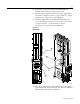
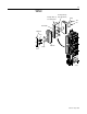
4. Position the copper plate, provided in the Snubber Board
Installation kit, over the screw holes in the bus bar.
5. Attach the plate to the bus bar and reconnect the original black
wire. Refer to “Torque Sequence” on page I-4. Refer to “Torque
Specifications” on page I-11 for final tightening.
6. Attach the Snubber Board to the Bus Bar. Finger-tighten the
screws, alternating from screw to screw, 1/4 turn at a time. Refer
to “Torque Sequence” on page I-4. Refer to “Torque
Specifications” on page I-11 for final tightening.
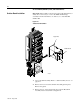
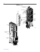
Figure I-11
Wiring Detail
7. Route the new white wire from the Snubber Board, through the
open channel under the heat sink, and to the other side of the Heat
Sink Assembly bus bar. Refer to Figure I-11.
AB0927
Snubber Board
Existing
Bus
White
Wire
Route
Wire