
Manual


1336-5.40 – August, 1999
I-16
1336 PLUS Drives
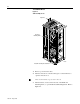
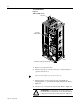
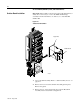
Figure I-8
SCR Assembly Access
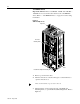
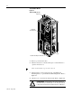
1. Remove power from the drive.
2. Turn the enclosure door latches 90 degrees counterclockwise to
open the enclosure door.
3. Turn the latches, located on the left side of the PC Board
Mountingframe,toopenthePCBoardMountingFrame.Referto
Figure I-8.
4. Check for zero volts between +DC and -DC. Refer to Figure I-6.
AB0963
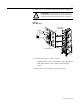
Input Lines
Heat Sink Assembly Ground Cable
PC Board
Mounting Frame
Drive shown with door open, sides removed.
!
ATTENTION: A blown fuse can create a hazard of
shockwhich mayresultin deathor serious injury. Check
voltage between the bus bar and both ends of all fuses.