
Manual


1336-5.40 – August, 1999
I-13
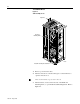
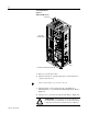
4. Check for zero volts between +DC and -DC. Refer to Figure I-6.
Figure I-6
DC Voltage Check
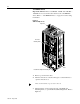
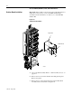
5. Check for the absence of control voltage at:
– TB20 and TB21 on drives using a PLC Comm Adapter Board
– TB5, TB6, and TB7 on drives using a Standard Adapter
Board
6. Remove the customer-supplied wiring from the drive.
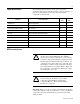
!
ATTENTION: A blown fuse can create a hazard of
shockwhich mayresultin deathor serious injury. Check
voltage between the bus bar and both ends of all fuses.
AB0930
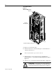
–DC (Negative
Capacitor Bus)
+DC
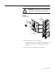
Check All Bus Fuses