
Manual


1336-5.40 – August, 1999
I-11
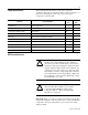
Torque Specifications
The following table lists fastener locations by component,
application, and torque specifications. Refer to “Torque Sequence” on
page I-4 for fastening two-point, four-point, and six-point
components to the heat sink.
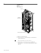
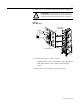
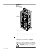
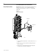
SCR Assembly Access
Important: Before you remove connections and wires from the drive
components, mark the connections and wires to correspond with their
component connections and terminals to prevent incorrect wiring
during assembly.
Component Fastener Application
Torque
in.-lb
Torque
N-m
Snubber Board Board to Copper Plate 7 0.8
SCR Assembly Assembly to heat sink 240 28
Converter Bus and Motor Bus Bars All connections 240 28
Wires (PE) Wires to Ground Stud 75 9
Wire (TE) Wire on Main Control Board Mounting Plate 6
Fan Connections Wires to TB1 12
PLC Comm Board Wires to TB2 7 0.8
Power Cables Cables to terminals 240 28
T-Bar Mounting Bolt T-Bar to Main Frame 240 28
Ground Cable Bolts Ground Cables from both assemblies to Main Frame Plate 175 21
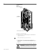
!
ATTENTION: Disconnect and lock out power from
the drive before disassembling the drive. Failure to
disconnect power may result in death or serious injury.
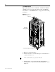
Verifybus voltageby measuring thevoltage betweenthe
Negative Capacitor Bus and both ends of all fuses. An
open fuse does not show voltage across both ends of the
fuse. Failure to measure voltage at bothends of the fuses
may result in death or serious injury. Referto Figure I-6.
Do not attempt to service the drive until the bus voltage
hasdischargedtozerovolts.
!
ATTENTION: Wear a wrist-type grounding strap
when servicing drives. Failure to protect drive
components against ESD may damage drive
components. Refer to “Electrostatic Discharge
Precautions”onpageI-4.