
Owner's manual


1336-5.49 – August, 1999
I-3
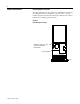
Where This Kit is Used You can use this kit to install a snubber board on the SCR module in
your drive.
What This Kit Contains This kit contains a snubber board assembly and these instructions.
SCR module testing and replacement information is included in these
instructions.
How to Use These Instructions To install a snubber board on your drive:
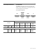
1. Determine the rating of the drive, refer to “Drive and Option
Identification” on page I-7.
2. Access the SCR module, refer to “SCR Module Access” on
page I-11.
3. Install the snubber board, refer to “Snubber Board Installation”
on page I-22.
If your drive is not working correctly, refer to “SCR Module Test” on
page I-24.
Safety Precautions
!
ATTENTION: Some printed circuit boards and drive
components may contain hazardous voltage levels.
Remove and lock out power before you disconnect or
reconnect wires, and before you removeor replacefuses
and circuit boards. Verify bus voltage by measuring the
voltage between +DC and -DC on Terminal Block TB1.
Do not attempt to service the drive until the bus voltage
has discharged to zero volts.
!
ATTENTION: Potentially fatal voltages may result
from improper usage of oscilloscope and other test
equipment. The oscilloscope chassis may be at a
potentially fatal voltage if not properly grounded. If an
oscilloscopeisusedtomeasurehighvoltagewaveforms,
use only a dual channel oscilloscope in the differential
mode with X 100 probes. It is recommended that the
oscilloscopebe usedin the A minusB Quasi-differential
mode with the oscilloscope chassis correctly grounded
to an earth ground.