
Owner's manual


1336-5.49 – August, 1999
I-25
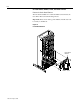
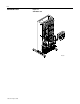
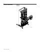
1. Access the SCR Module. Refer to “SCR Module Access” on
page I-11.
2. Set your meter to test diodes.
3. The following table shows meter connections and ideal meter
readings for those connections. Refer to Figure I-11 for meter
connection locations.
Note: Typical malfunction is shorted in both directions.
Note: Meter Used: Fluke®
Model 87, set to “Diode” range.
4. Replace the SCR Module if any meter readings are not as shown.
Refer to “SCR Module Replacement” on page I-26.
5. If the SCR Module shorted, check the IGBT for damage.
Important: Refer to your Service or Troubleshooting Manual for
IGBT Module test information.
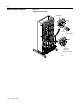
Assemble the drive in reverse order of removal. Refer to “Torque
Sequence” on page I-4. Refer to “Torque Specifications” on page I-11
for final tightening.
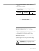
Meter (+) Lead Meter (-) Lead
Nominal Meter Reading
Volts Ohms
No test information at this time.
Test information will be included when it is available.
!
ATTENTION: Replace all guards before applying
power to the drive. Failure to replace guards may result
in death or serious injury.