
Owner's manual


1336-5.49 – August, 1999
I-21
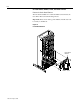
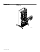
1. Disconnect both ground wires from TB5 located in the lower
right-hand corner of the Main Control Board Mounting Plate.
2. Disconnect the following from the Main Control Board:
– J1 connector
– J2 connector
– TB3, if Option Board is used
– any optional boards
3. Remove the two nuts from the top and the bottom of the Main
Control Board Mounting Plate.
4. Pull the Main Control Board Mounting Plate straight out of the
drive.
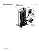
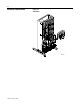
5. Disconnect the following from the Gate Driver Board:
– J2 connector
– J7 connector
– J8 connector
– J10 connector
6. Disconnect the following from the Precharge Board:
– J1 connector
– J2 connector
– J4 connector
7. Disconnect the two LEM wire harness plugs.
8. Remove the four nuts fastening the Circuit Board Platform to the
drive.
9. Pull the Circuit Board Platform straight out of the drive.