
Owner's manual


1336-5.49 – August, 1999
I-13
1. Remove power from the drive.
2. Open the Enclosure door.
3. Check for zero volts at:
–+DC/-DCBrakeTerminals
– terminalsR-L1,S-L2,andT-L3onTB1
4. Check for the absence of control voltage at:
– terminals V+ and V- on TB11 on the Main Control Board
– TB20 and TB21 on drives using a PLC Comm Adapter Board
– TB5, TB6, and TB7 on drives using a Standard Adapter
Board
– TB3 on drives using a Control Interface L-Option Board
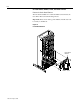
5. Remove the four nuts fastening the High Voltage Guard to the
standoffs.
6. Pull the guard away from the drive.
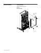
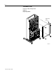
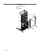
Drive shown with door open, sides removed.