
Owner's manual


1336-5.49 – August, 1999
I-11
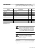
Torque Specifications The following table lists fastener locations by component,
application, and torque specifications. Refer to “Torque Sequence” on
page I-4 for fastening two-point, four-point and six-point components
to the heat sink.
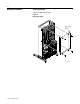
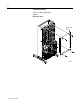
SCR Module Access
Important: Before you remove connections and wires from the drive
components, mark the connections and wires to correspond with their
component connections and terminals to prevent incorrect wiring
during assembly.
Component Fastener Application
Torque
in.-lb
Torque
N-m
Snubber Board Board to SCR 50 6
SCR Module Module to heat sink 50 6
Wires (PE) Wires to Ground Stud 80 9
Wires Wires to TB1 80 9
Wire (TE) Wires to TB1 50 6
Wires Wires to TB2 7 0.8
Wires Wires to TB3 8 – 10 09 – 1.1
Power Cables Cables to terminals 208 23
Control Board Platform Plates to chassis 26 3
High Voltage Guard Guard to chassis 26 3
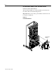
!
ATTENTION: Disconnect and lock out power from
the drive before disassembling the drive. Failure to
disconnect power may result in death or serious injury.
Verify bus voltage by measuring the voltage between
+DC and -DC on Terminal Block TB1. Do not attempt
to service the drive until the bus voltage has discharged
to zero volts.
!
ATTENTION: Wear a wrist-type grounding strap
when servicing drives. Failure to protect drive
components against ESD may damage drive
components. Refer to “Electrostatic Discharge
Precautions”onpageI-4.