
Manual


Heavy Duty Dynamic Braking
2
4
1336-5.64 — July, 2005
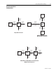
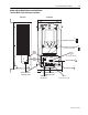
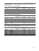
KB050 and KC050
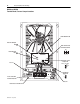
Terminal Block, Fuse and Jumper Locations
Power and Control
Terminal Block TB1
TB3
12
Fuse F2
Input Voltage Select
Jumper W2
KB050 Units Only
Brake Chassis Ground Screw
Brake Fault Contact
Terminal Block TB3
Brake Module Board
DS1
DC Power ON Light
Fuse F1
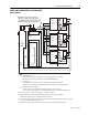
DS1
V. SEL
M
W1
W2
S
380V
TB3
Slave/Master
Jumper W1
3
2
1
DS2
Brake ON Light
DS2
460V
3
W2
W1
2
1
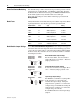
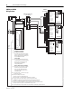
V SELECT
380V
SLAVE IN.
(+) ( –)
DC BUS
( –) (+)
120VAC
POWER
120VAC
ENABLE
TERMINAL STRIP TB–1
MASTER OUT
(–) ( +)
1
2
345
67
8
910
460V
M
S
3
2
1