
Owner's manual


I–2 Index
I
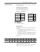
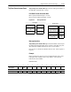
image table
blank, 2-4
example, 2-4
illustration, 4-2
understanding, 4-1
installing a Remote I/O communications
module, 3-3, 3-6
L
ladder logic programs, 4-1
last rack, 2-9
LEDs, 6-1, 6-2
links
example, 1-2
terminating, 3-2
logic command
example bits, 4-6
setting switch for, 2-5
logic status
example bits, 4-7
setting switch for, 2-5
Logix5550 controllers
block transfers, 5-7
compatible, 1-3
ladder logic programs, 4-12
M
manual
audience, P-1
contents, P-2
online, P-2
purpose, P-1
related documentation, P-2
mounting a board, 3-7
N
NVS (Non-Volatile Storage), B-16
P
Parameter Read Full block transfer, B-5
Parameter Value Read block transfer,
B-3
Parameter Value Write block transfer,
B-4
PLC controllers
block transfers, 5-3
compatible, 1-3
ladder logic programs, 4-8
Product ID Number Read block transfer,
B-8
products
compatible, 1-3
definition, P-2
see also SCANport products
supporting datalinks, 4-2
programs, 4-1
R
rack
address, 2-12
last, 2-9
size, 2-4, 2-8
reference, 2-6
related documentation, P-2
Rem I/O ACT LED, 6-1, 6-2
Rem I/O STS LED, 6-1, 6-2
Remote I/O
baud rate, 2-11
cables, 3-2, 3-4, 3-7
definition, P-2
example link, 1-2
terminating links, 3-2
Remote I/O communications module
compatibility, 1-3
definition, P-2
description, 1-1
features, 1-2
illustration, 1-4, 1-5
installing, 3-3, 3-6
parts, 1-4, 1-5
specifications, A-1
types, 1-1
removing SCANport cables, 3-1
required equipment, see equipment
resistor, see termination resistor