
Owner's manual

4–12 Creating Ladder Logic Programs
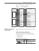
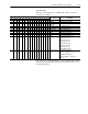
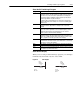
Example Logix5550 Ladder
Logic Program
Refer to page 4–5 for the settings of the module and the 1336 PLUS
drive used for this example.
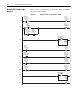
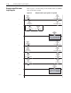
Figure 4.6 Example Ladder Logic Program for a Logix5550
0
Machine
Start
Pushbutton
Local:2:I.Data.1
Drive
START
Command
Bit
PLUS_IO:O.Data[1].1
1
Machine
Stop
Pushbutton
Local:2:I.Data.0
Drive
STOP
Command
Bit
PLUS_IO:O.Data[1].0
Drive
RUNNING
Status
Bit
PLUS_IO:I.Data[1].1
Drive
STOP
Command
Bit
PLUS_IO:O.Data[1].0
2 Move
Source Reference
0
Dest PLUS_IO:O.Data[2]
2#0000_0000_0000_0000
MOV
Drive
Frequency
Reference
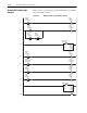
3
Machine
JOG
Pushbutton
Local:2:I.Data.2
Drive
JOG
Command
Bit
PLUS_IO:O.Data[1].2
4
Machine
CLEAR
FAULTS
Pushbutton
Local:2:I.Data.3
Drive
CLEAR
FAULTS
Command
Bit
PLUS_IO:O.Data[1].3
5
Drive
RUNNING
Status
Bit
PLUS_IO:I.Data[1].1
Machine
RUNNING
Indicator
Lamp
Local:3:O.Data.0
6
Drive
FAULTED
Status
Bit
PLUS_IO:I.Data[1].7
Machine
FAULTED
Status
Bit
Local:3:O.Data.1
7 Move
Source PLUS_IO:I.Data[2]
2#0000_0000_0000_0000
Dest Feedback
0
MOV
Drive
Frequency
Feedback
(End)