Allen-Bradley Bulletin 1203 Remote I/O Communications Module Cat. Nos. 1203-GD1, 1203-GK1, or 1336-GM1 Firmware 1.xx – 4.
Important User Information Because of the variety of uses for the products described in this publication, those responsible for the application and use of this control equipment must satisfy themselves that all necessary steps have been taken to assure that each application and use meets all performance and safety requirements, including any applicable laws, regulations, codes and standards.
Summary of Changes The information below summarizes the changes made to this manual since the last release. Updated Information This manual incorporates the information found in the following two manuals: • Bulletin 1203 Remote I/O Communication Module Getting Started Manual, Publication 1203-5.1. • Bulletin 1203 Remote I/O Communications Module Reference Manual, Publication 1203-5.0. It also contains new information.
2 End of Summary of Changes
Table of Contents Preface Using This Manual Preface Objectives . . . . . . . . . . . . . . . . . . . . . . . . . . . . . . . . . . . . . . . . . . Audience for This Manual . . . . . . . . . . . . . . . . . . . . . . . . . . . . . . . . . . . . . Purpose of This Manual . . . . . . . . . . . . . . . . . . . . . . . . . . . . . . . . . . . . . . Firmware Support . . . . . . . . . . . . . . . . . . . . . . . . . . . . . . . . . . . . . . . . . . . Terms and Abbreviations. . . . . . . . . . . . . . . . . . . .
ii Table of Contents Chapter 5 Using Block Transfer Messages Chapter Objectives. . . . . . . . . . . . . . . . . . . . . . . . . . . . . . . . . . . . . . . . . . . 5-1 Understanding Block Transfer . . . . . . . . . . . . . . . . . . . . . . . . . . . . . . . . . . 5-1 Understanding the Block Transfer Status Word . . . . . . . . . . . . . . . . . . . . . 5-2 Understanding Data Storage . . . . . . . . . . . . . . . . . . . . . . . . . . . . . . . . . . . 5-3 Example PLC Block Transfers . . . . . . . . .
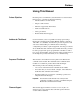
Preface Using This Manual Preface Objectives Audience for This Manual Read this preface to familiarize yourself with the rest of the manual. In this preface, you will read about the following: • Intended audience for this manual. • Purpose of this manual. • Firmware supported by this manual. • Terms and abbreviations. • Safety precautions. • Rockwell Automation support.
P–2 Using This Manual Contents of this Manual Chapter Preface 1 2 3 4 5 6 A B Title Using This Manual Contents Descriptions of the audience, purpose, background, and scope of this manual. Overview Features of the Remote I/O communications module. Configuring the Module Procedures for setting DIP switches. Installing the Module Procedures for mounting, connecting cables, and connecting power. Creating Ladder Logic Information about addressing, information transPrograms fer, and sample programs.
Using This Manual P–3 Safety Precautions ! ! ! ATTENTION: Only personnel familiar with SCANport devices and associated machinery should plan or implement the installation, start-up, configuration, and subsequent maintenance of the Remote I/O communications module. Failure to comply may result in personal injury and/or equipment damage. ATTENTION: The 1336-GM1 board contains Electrostatic Discharge (ESD) sensitive parts and assemblies.
P–4 Using This Manual Rockwell Automation Support Rockwell Automation offers support services worldwide, with more than 75 sales/support offices, more than 500 authorized distributors, and more than 250 authorized systems integrators located throughout the United States alone. In addition, Rockwell Automation representatives are in every major country in the world. Local Product Support Contact your local Rockwell Automation representative for: • Sales and order support. • Product technical training.
Chapter 1 Overview Chapter Objectives Chapter 1 provides an overview of the Remote I/O communications module (1203-GD1 module, 1203-GK1 module, and 1336-GM1 board). In this chapter, you will read about the following: • Function of the module. • Features of the module. • Compatible SCANport products and programmable controllers. • Parts and hardware of the module. • Steps for setting up the module. • Required tools and equipment.
1–2 Overview The 1203-GD1 and 1203-GK1 modules mount on a DIN rail. They connect to a SCANport product using a SCANport cable and to the Remote I/O link using a Remote I/O cable. The 1336-GM1 board mounts directly onto selected SCANport products. It connects to a SCANport product using an internal SCANport connector and to the Remote I/O link using a Remote I/O cable. Figure 1.2 shows how the modules connect SCANport products to the Remote I/O link. Figure 1.
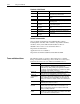
Overview Compatibility 1–3 SCANport Products Remote I/O modules are compatible with many SCANport products, including the following: Product 1305 AC MICRO Drive➀ 1336 IMPACT™ Drive 1336 PLUS AC Drive 1336 PLUS II Drive 1336 FORCE™ Drive 1336 REGEN Line Regeneration Package 1336 SPIDER Drive 1394 AC Mult-Axis Motion Control System SMC Dialog Plus™ SMP-3 Smart Motor Protector 1397 Digital DC Drive 1557 Medium Voltage Drive 2364F Regenerative DC Bus Supply Unit Number of Peripherals Supported 5 6➁ 6➁ 6➁ 6
1–4 Overview Hardware Description The hardware included with the module depends on the module that you have. 1203-GD1 and 1203-GK1 Modules The 1203-GD1 module and 1203-GK1 module share the same parts. Figure 1.3 illustrates these parts. Figure 1.3 Parts of the 1203-GD1 and 1203-GK1 Module 1 3 2 4 6 5 # 1 Part SCANport Connection Description Standard SCANport 8-pin mini-DIN connector for the SCANport cable. 2 Power Supply Connections Connections for the power supply.
Overview 1–5 1336-GM1 Board Hardware Figure 1.4 illustrates the main parts of a 1336-GM1 board. Figure 1.4 Parts of the 1336-GM1 Board 4 3 1 2 # 1 2 3 Part SCANport Connection Remote I/O Connection LEDs 4 DIP Switches Not Kit Shown Description Internal 14-pin female SCANport connector. Standard 3-pin Remote I/O connector. Status indicators for the module, SCANport connection, and Remote I/O connection. Refer to Chapter 6. Switches used to configure the module. Refer to Chapter 2.
1–6 Overview Required Tools and Equipment The tools and equipment required, depend on if you are using a 1203-GD1 module, 1203-GK1 module, or 1336-GM1 board. 1203-GD1 or 1203-GK1 Module To install and configure a 1203-GD1 module or 1203-GK1 module, you need the following: • Remote I/O communications module (1203-GD1 or 1203-GK1). • 35 x 7.5 mm DIN rail. • Termination resistor(s). • Power source. • 1/8" flathead screwdriver. • Appropriate cables for SCANport and Remote I/O connections.
Chapter 2 Configuring the Module Chapter Objectives Chapter 2 provides instructions and information for configuring the Remote I/O communications module (1203-GD1, 1203-GK1, or 1336-GM1). In this chapter, you will read about the following: • Factory-default settings. • Recording the I/O image table. • Configuring the module. Important: The communications module is not compatible with complementary I/O configurations because it uses both output and input image words for proper product control.
2–2 Configuring the Module Locating the DIP Switches Figure 2.1 SW3.1 = Block Transfer SW3.2 = Logic Command/Status SW3.3 = Reference/Feedback SW3.4 = Datalink A Settings SW3.5 = Datalink B Settings SW3.6 = Datalink C Settings SW3.7 – Datalink D Settings SW3.8 = Truncate Last Datalink Switches on the 1203-GD1 and 1203-GK1 Modules SW2.1 – SW2.2 = Starting Module Group SW2.3 = Last Rack Setting SW2.4 = Hold Last State/Zero Data SW2.5 = Communications Loss SW2.6 = Reset/Program/Test SW1.1 – SW1.
Configuring the Module Factory-Default Settings Quick Configuration 2–3 The module is shipped with the following settings: Feature Block Transfer Logic Command/Status Reference/Feedback Datalinks Switch(es) 3.1 3.2 3.3 3.4 – 3.7 Truncate Last Datalink Starting Group Last Rack Fault Action 3.8 2.1 – 2.2 2.3 2.4 – 2.6 Baud Rate Not Used Rack Address 2.7 – 2.8 1.1 – 1.2 1.3 – 1.
2–4 Configuring the Module Configuring the module As you configure your module, you should complete the I/O image table. First, size the I/O using switch SW3. Next, set the rack address using switch SW1. Finally, select the starting group, last rack setting, fault action, and baud rate using switch SW2. For more information on the I/O image table, refer to the example below and Chapter 4.
Configuring the Module 2–5 Setting Switches on SW3 ! ATTENTION: Injury or equipment damage can result from loss of PLC or Controller Logic Commands (Stop, Start, etc.) when all these conditions are true: • module firmware 3.04 or lower. • 230.4k baud rate. • block transfer is enabled (DIP switch SW3-1 is ON). • block transfers to the module are used (in the ladder program or by DriveTools/DriveTools32 using a Remote I/O pass thru connection). Do not use the 230.
2–6 Configuring the Module Important: Due to an anomaly in firmware release 4.01, Remote I/O modules that are used only for block transfer messages require the following configuration: switches for block transfer and reference/feedback should both be enabled (SW 3.1 and SW 3.3 are ON. SW 3.2 and SW 3.4 through 3.8 are OFF). This configuration prevents a fault on power up. It does not affect rack I/O allocation or the ladder logic program because it still fits within 1/4 rack I/O space.
Configuring the Module Figure 2.5 2–7 Reference/Feedback Switch Off = 0 On = 1 Use SW 3.3 for setting the command I/O To edit the reference/feedback setting, you need to: 1. Refer to the following table to determine the setting for SW 3.3: Reference/Feedback Disabled Enabled SW 3.3 0 1 2. Slide the switch to its appropriate position. 3.
2–8 Configuring the Module Setting Datalinks SW 3.7 through SW 3.4 enable or disable datalinks. A datalink is a type of pointer used by some SCANport products to transfer data to and from a controller. You can use datalinks to change or monitor the value of parameters without using block transfer messages. Each datalink consists of two 16-bit words of input and two 16-bit words of output. You can enable up to four datalinks (eight words in and out).
Configuring the Module Figure 2.7 2–9 Truncate Last Datalink Switch Off = 0 On = 1 Use SW 3.8 for truncating the last datalink. To set the truncate last datalink feature, you need to: 1. Refer to the following table to determine the setting for SW 3.8: Duplicate Message Detection Disable Enable SW 3.8 0 1 2. Slide the switch to its appropriate position. 3. If the switch is enabled, cross out the second module group (word) of the last datalink in your I/O image table on page 2–4.
2–10 Configuring the Module 2. Refer to the following table to set SW 2.2 and SW 2.1: Starting Group 0 2 4 6 SW 2.2 1 0 1 0 SW 2.1 1 1 0 0 3. Slide the switches to their appropriate positions. Settings take effect when a module or board first receives power. When you change a setting, you must remove and then reapply power for the new setting to take effect. Setting the Last Rack Switch SW 2.3 lets you notify a controller that the connected product is the last device with this rack address.
Configuring the Module 2–11 Setting the Fault Action SW 2.6 through SW 2.4 let you configure how a Remote I/O module and connected product act when Remote I/O communications fail (e.g., disconnected cable) or the controller is switched to program or test mode. You can use fault, hold last state, or zero data. If you select hold last state, a product continues in its present state after a communications disruption. If you select zero data, the data output to the product is zeroed.
2–12 Configuring the Module 4. Slide the switches to their appropriate positions. Settings take effect when a module or board first receives power. When you change a setting, you must remove and then reapply power for the new setting to take effect. Setting the Remote I/O Baud Rate SW 2.8 and SW 2.7 set the baud rate at which the Remote I/O module communicates. ! ATTENTION: Injury or equipment damage can result from loss of PLC or Controller Logic Commands (Stop, Start, etc.
Configuring the Module Setting Switches on SW1 2–13 Setting the Rack Address DIP switches 8 through 3 on SW 1 set the rack address for the Remote I/O module. Each Remote I/O device must have a rack address that the controller can recognize. Each rack contains 8 words. Important: When using a PLC-2 family processor, add 1 to the rack number set on the Remote I/O module DIP switches to your PLC code.
2–14 Configuring the Module
Chapter 3 Installing the Module Chapter Objectives Chapter 3 provides the information that you need to install the module (1203-GD1 module, 1203-GK1 module, or 1336-GM1 board). In this chapter, you will read about the following: • Selecting cables. • Selecting a termination resistor. • Installing a 1203-GD1 or 1203-GK1 module. • Installing a 1336-GM1 board.
3–2 Installing the Module Remote I/O Cables Remote I/O communications modules are connected to Remote I/O links with twinaxial cable used for Remote I/O and Data Highway Plus (DH+) communications. When selecting a cable, remember the following: • Only 1770-CD Belden #9463 is tested and approved for RIO and DH+ installations. Using other cables is at your own risk. • The total cable length depends on the baud rate that you are using. Refer to the following table: Baud Rate 57.6 K 115.2 K 230.
Installing the Module Installing a 1203-GD1 or 1203-GK1 Module 3–3 Required Tools and Equipment To install your module, you need the following tools and equipment: • Remote I/O communications module (1203-GD1 or 1203-GK1). • 35 x 7.5 mm DIN rail. • Appropriate cables for SCANport and Remote I/O connections. Refer to the “Selecting Cables” section in this chapter. • Termination resistor (if necessary). Refer to the “Selecting a Termination Resistor” section in this chapter.
3–4 Installing the Module 3. Connect a SCANport cable (1202-Cxx) to a module and product. Important: For the location of the SCANport connector on your product, refer to its user manual. If you are using a port expander, refer to its documentation. Figure 3.2 Connecting the SCANport Cable SCANport Product . Module 4. Connect a Remote I/O cable to the module and link or controller. Figure 3.3 Connecting the Remote I/O Cable PLC Controller Blue Shield Clear .. .
Installing the Module 3–5 5. If the module is the last device on the Remote I/O link, connect the termination resistor. If the Remote I/O link uses 230Kbps, you must use an 82 ohm termination resistor. Figure 3.4 Connecting the Termination Resistor 2 Clear Shield I50 Ohm or 82 Ohm 1 watt +/-10% Sh Blue To Another Remote I/O Link Device 1 6. Connect the power supply to the module. Figure 3.
3–6 Installing the Module Installing a 1336-GM1 Board Required Tools and Equipment To install your 1336-GM1 board, you need the following tools and equipment: • Remote I/O communications board (1336-GM1). • A kit that includes one grounding wrist strap, four Phillips mounting screws, four stand-off nylon headers, and one snap-in comm housing with mounting instructions (supplied with board). • #1 Phillips screwdriver. • Appropriate cable for the Remote I/O connection.
Installing the Module 3–7 4. Screw the four stand-off nylon headers into the appropriate spaces on the drive main control board. Figure 3.6 Mounting the Open Style Communications Board 5. Insert the SCANport connector into the 14-pin SCANport header on the control board. The DIP switches should be facing you. 6. Screw the board securely into place, being careful not to overtighten the four screws. 7. Connect the Remote I/O cable. Figure 3.
3–8 Installing the Module 8. If the module is the last device on the Remote I/O link, either user the internal termination resistor (J2) or an external termination resistor. If the Remote I/O link uses 230Kbps, you must use an external 82 ohm termination resistor. Important: Use only one type of termination (internal or external), Figure 3.
Chapter 4 Creating Ladder Logic Programs Chapter Objectives Chapter 4 provides information about ladder logic programs for products connected to a Remote I/O communications module. In this chapter, you will read about the following: • I/O image table. • Control Features. • Datalinks. • Example ladder logic programs for PLC, SLC, and Logix5550 controllers.
4–2 Creating Ladder Logic Programs DIP switches on SW3 determine how the data contained in the programmable controller I/O image table is used in the drive. Figure 4.1 shows an I/O image table. Figure 4.
Creating Ladder Logic Programs 4–3 Products That Support Datalinks To use datalinks, your SCANport product must support them. Refer to your product user manual. Using Datalinks The following are the rules for using datalinks: • Normally, each enabled datalink reserves two words in both the input and output image tables of the controller. This increases your I/O image size. The starting module group on the module must be set to support the size of the I/O image table.
4–4 Creating Ladder Logic Programs Example Application 2 Another application for datalinks is to set a parameter into a Data Out parameter. The controller input image table word connected to this datalink will then receive the value of the parameter programmed into the Data Out parameter. For example, to monitor the value of parameter 27 in a 1336 PLUS drive, you need to: 1. In the 1336 PLUS drive, set parameter 119 (Data Out A1) to 27. 2. On the module, slide SW 3.4 to ON. See Figure 2.6. 3.
Creating Ladder Logic Programs 4–5 Figure 4.2 illustrates the first scan in Example Application 3. Figure 4.
4–6 Creating Ladder Logic Programs SCANport Product Settings Logic Command bits In our example, we are using a 1336 PLUS drive.
Creating Ladder Logic Programs 4–7 Logic Status Bits The Logic Status bits for the 1336 PLUS drive that we use in our example are as follows: 15 14 13 12 11 Logic Status Bits 10 9 8 7 6 5 4 3 2 1 X X X X X X X X X X X X X X X 0 Function X Enabled Running Command Direction Rotating Direction Acceleration Deceleration Warning Fault At Speed Local Reference Source Description 1=Enabled, 0=Not Enabled 1=Running, 0=Not Running 1=Forward, 0=Reverse 1=Forward, 0=Reverse 1=Accelerating, 0=Not
4–8 Creating Ladder Logic Programs Example PLC Ladder Logic Program Refer to page 4–5 for the settings of the module and the 1336 PLUS drive used for this example. Figure 4.
Creating Ladder Logic Programs 4–9 About the PLC Ladder Logic Program Rung 0001 0002 0003 0004 0005 0006 0007 0008 Description When the machine Start push button is pressed, the PLC sends a START command to the drive. The drive will start if no STOP command is being sent by the PLC or any other control device. (Start button is a normally open contact in this example.) SCANport products will start only if the start bit transitions high while the stop bit is already low.
4–10 Creating Ladder Logic Programs Example SLC Ladder Logic Program Refer to page 4–5 for the settings of the module and the 1336 PLUS drive used for this example. Figure 4.
Creating Ladder Logic Programs 4–11 About the SLC Ladder Logic Program Rung 0001 0002 0003 0004 0005 0006 0007 0008 Description When the machine Start push button is pressed, the SLC sends a START command to the drive. The drive will start if no STOP command is being sent by the SLC or any other control device. (Start button is a normally open contact in this example.) SCANport products will start only if the start bit transitions high while the stop bit is already low.
4–12 Creating Ladder Logic Programs Example Logix5550 Ladder Logic Program Refer to page 4–5 for the settings of the module and the 1336 PLUS drive used for this example. Figure 4.6 0 1 4 5 6 7 (End) Drive START Command Bit PLUS_IO:O.Data[1].1 Machine Start Pushbutton Local:2:I.Data.1 Drive STOP Command Bit PLUS_IO:O.Data[1].0 Machine Stop Pushbutton Local:2:I.Data.0 Drive Drive STOP RUNNING Command Status Bit Bit PLUS_IO:O.Data[1].0 PLUS_IO:I.Data[1].
Creating Ladder Logic Programs 4–13 About the Logix5550 Ladder Logic Program Rung 0001 0002 0003 0004 0005 0006 0007 0008 Description When the machine Start push button is pressed, the Logix5550 sends a START command to the drive. The drive will start if no STOP command is being sent by the Logix5550 or any other control device. (Start button is a normally open contact in this example.) SCANport products will start only if the start bit transitions high while the stop bit is already low.
4–14 Creating Ladder Logic Programs End of Chapter 4
Chapter 5 Using Block Transfer Messages Chapter Objectives Chapter 5 provides information about Block Transfer messages. In this chapter, you will read about the following: • General information on block transfers. • The Remote I/O status word. • Data storage. • Example ladder logic programs using Block Transfer messages. ! ! Understanding Block Transfer ATTENTION: The sample programs and block transfer examples shown in this manual are intended solely for purposes of example.
5–2 Using Block Transfer Messages Understanding the Block Transfer Status Word The block transfer status word is returned from the Remote I/O module. It is the first word associated with the rack in the controller input image table. This status word indicates the condition of the Remote I/O module itself and is not part of the standard block transfer instructions in the ladder program. Figure 5.1 details the individual bits. Figure 5.
Using Block Transfer Messages 5–3 Understanding Data Storage In order to use the block transfer instructions in the ladder program, it is necessary to reserve several words for data storage. Some of these words are required for internal use by the block transfer function, and some contain the block transfer message information. Refer to Appendix B for detailed information on the required data in data files for different block transfer messages. Example PLC Block Transfers Figure 5.3 and Figure 5.
5–4 Using Block Transfer Messages Figure 5.4 Example for a PLC-5/20, PLC-5/40, PLC-5/60, PLC-5/80 This rung performs a Block Transfer Write to the 1203-GD1 at Rack Address 1, Starting Group 0 (the Module number is always 0 with these adatpers). The data instructs the adapter to send a SCANport message. When this message has completed, the response can be read with a BTR.
Using Block Transfer Messages Example SLC Block Transfers 5–5 Figure 5.5 and the following data file illustrate an example block transfer program from an SLC controller to a Remote I/O communications module. This program uses the first block transfer area in the scanner located in the first slot. It also uses data files N10 and B3. The example data file contains the data needed to request a read full of parameter 78. The length of the block transfer data file is loaded into N10:1.
5–6 Using Block Transfer Messages Figure 5.5 SLC Block Transfer Continued When the Gx1 indicates that it is ready for a BTR, this rung sets up the BT buffer for a BTR and enables it. BTR Available I:1.0 Virtual BT.Type Bit 0 = BTW 1 = BTR N10:0 L 7 Virtual BT.EN Bit N10:0 0004 10 1747-SN 15 Virtual BT.EN Bit N10:0 L 15 Virtual BT.
Using Block Transfer Messages 5–7 Calculating the Rack, Group, Slot Address The Rack, Group, Slot address for a block transfer is calculated as shown in the table below. Rack, Group, Slot Address 0,0,0 1,0,0 1,2,0 2,4,0 Decimal Value 0 100 120 240 This value is needed as part of the data file that is copied to the M0-file block transfer buffer in the 1747-SN RIO Scanner module. Example Logix5550 Block Transfers Figure 5.
5–8 Using Block Transfer Messages Figure 5.6 Example for a Logix5550 Due to the asynchronous nature of the ControlLogix platform, input data may change during a program scan. This rung makes a local copy of the Block Transfer Status word to ensure proper synchronization between the ControlLogix program and the RIO Scanner. Make a Local Copy of the 1203-GD1's Block Transfer Status Word MOV Move Source PLUS_IO:I.
Chapter 6 Troubleshooting Chapter Objectives Chapter 6 provides information about the LEDs on the Remote I/O modules. It also provides basic troubleshooting procedures. In this chapter, you will read about the following: • Locating the LEDs. • Using the LEDs to troubleshoot. LEDs on the Remote I/O Communications Module Figure 6.
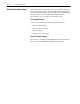
6–2 Troubleshooting FAULT LED LED Status Red (Steady) Red (Blinking) Cause • Unrecoverable Fault • Recoverable Fault • If Health LED is steady, a DIP switch is set incorrectly, there is a bad cable, or an RIO connection between the controller and adapter has not been made. Off • Normal Operation Corrective Action • Replace the module. • Verify that the module is configured correctly. • Verify that the SCANport and Remote I/O cables are correctly wired and securely connected.
Appendix A Specifications Appendix Objectives Appendix A provides the specifications for the 1203-GD1 module, 1203-GK1 module, and the 1336-GM1 board. Important: Remote I/O communications modules are non-repairable units. 1336-GM1 Board Specifications The following table gives the specifications for the 1336-GM1 board.
A–2 Specifications 1203-GD1 Module Specifications The following table gives the specifications for the 1203-GD1 module.
Appendix B Supported Block Transfer Messages Appendix Objectives Appendix B provides information about the Block Transfer messages supported by the Remote I/O communications module. In this appendix, you will read about the following: • Block transfer status word. • Setting up data files for block transfer messages. • Examples of block transfer messages. • Block transfer quick reference. Important: This appendix provides detailed examples of block transfer messages.
B–2 Supported Block Transfer Messages Block Transfer Data Structure Successful Messages When an operation is successful, header word 1 of the drive response contains a positive value (bit 15 = 0) and data follows. Figure B.
Supported Block Transfer Messages Parameter Value Read B–3 Parameter Value Read reads the 16-bit parameter data value for the selected parameter number. PLC Block Transfer Instruction Data PLC request instruction length: 3 words Drive response instruction length: 4 words Figure B.
B–4 Supported Block Transfer Messages Parameter Value Write Parameter Value Write writes a 16-bit parameter data value to the selected parameter number. PLC Block Transfer Instruction Data PLC request instruction length: 4 word Drive response instruction length: 4 words Figure B.
Supported Block Transfer Messages Parameter Read Full B–5 Parameter Read Full provides all known attributes for the parameters requested. This information includes the parameter’s current value, descriptor, multiply and divide value, base value, offset value, text string, group element reference, minimum value, maximum value, default value, and unit text string. PLC Block Transfer Instruction Data PLC request instruction length: 3 words Drive response instruction length: 23 words Figure B.
B–6 Supported Block Transfer Messages Message Structure (Continued) Drive Response (cont.) File, Group, Element Data Word 17 Minimum Value Data Word 18 Maximum Value Data Word 19 Default Value Char 2 Char 1 Char 4 Char 3 Unit Text Data Word 20 Data Word 21 Data Word 22 Message Operation Parameter Read Full retrieves the attributes of the specified parameter. The attributes for each parameter include the data, minimum and maximum values, and the parameter text.
Supported Block Transfer Messages B–7 This example shows the response message in both binary and ASCII. Note the ASCII information beginning with word 9. The parameter name characters return in reverse order for each word. Word 9 has the ASCII value of (aM). To read this, reverse the word to read (Ma). The next word (ix), reversed, gives you (xi). These words, along with the following two words, form the word Maximum.
B–8 Supported Block Transfer Messages Product ID Number Read Product ID Number Read returns the product ID of the device to which the Remote I/O module is connected. PLC Block Transfer Instruction Data PLC request instruction length: 3 words Drive response instruction length: 4 words Figure B.
Supported Block Transfer Messages B–9 Example In this example, the Product ID Number Read was requested. The drive response contained a value of 3 in word 3 of its message response, indicating a connection to a 1336 PLUS drive. Data File Format 0 1 2 PLC request 3 256 0 Drive Response 4 256 0 3 4 5 6 7 8 3* * Example only — These values vary depending on parameters and products.
B–10 Supported Block Transfer Messages Scattered Parameter Value Read Scattered Parameter Value Read reads a scattered list of parameters. PLC Block Transfer Instruction Data PLC request instruction length: 5 – 64 words Drive response instruction length: 5 – 64 words Figure B.
Supported Block Transfer Messages B–11 If an error has occurred in reading any of the parameters: • Word 1 of the drive response returns a value of –32765. • Bit 15 of the drive response word for the number of that parameter is set. • The drive response word for the value of that parameter returns a status word instead of returning the parameter value. Example In this example, eight parameters were read from a 1336 PLUS drive, as defined in word 2 of the request.
B–12 Supported Block Transfer Messages Scattered Parameter Value Write Scattered Parameter Value Write writes to a scattered list of parameters and returns the status of each parameter. If any of the states have errors, the parameter number is negative. PLC Block Transfer Instruction Data PLC request instruction length: 5 – 64 words Drive response instruction length: 5 – 64 words Figure B.
Supported Block Transfer Messages B–13 If an error occurs while writing to any of the parameters: • Word 1 of the drive response returns a value of –32765. • Bit 15 of the drive response word for that parameter’s number is set. • The drive response word for that parameter’s status word is non-zero. If no error has occurred: • Word 1 of the drive response returns a value of 3. • Each of the drive response’s parameter numbers are the same as in the request.
B–14 Supported Block Transfer Messages Continuous Parameter Value Read Continuous Parameter Value Read reads a continuous list of parameters beginning with the starting parameter number. PLC Block Transfer Instruction Data PLC request instruction length: 4 words Drive response instruction length: 5 – 64 words Figure B.
Supported Block Transfer Messages B–15 Example In this example, 60 parameters were read from a 1336 PLUS drive, beginning with parameter 10. The values of these parameters are returned in the response. The values are in Drive Units.
B–16 Supported Block Transfer Messages Save/Recall/Initialize Save/Recall/Initialize—NVS (Non-Volatile Storage) Functions— activates the specified function. These functions are also referred to as EEPROM functions. PLC Block Transfer Instruction Data PLC request instruction length: 4 words Drive response instruction length: 4 words Figure B.
Supported Block Transfer Messages Fault Command Write B–17 Fault Command Write activates the Clear Fault, Clear Fault Queue, and Drive Reset functions. PLC Block Transfer Instruction Data PLC request instruction length: 4 words Drive response instruction length: 4 words Figure B.
B–18 Supported Block Transfer Messages Fault Queue Entry Read Full Fault Queue Entry Read Full reads the contents of the specified fault queue entry. A message is returned which includes the fault text and fault code associated with the fault. The 1336 FORCE drive also returns the time stamp associated with the fault. PLC Block Transfer Instruction Data PLC request instruction length: 3 words Drive response instruction length: 12 or 16 words Figure B.
Supported Block Transfer Messages B–19 Message Operation Fault Queue Entry Read Full reads the contents of the fault queue specified in word 3 of the request. The response returns the fault text which can be ASCII text. Every two characters of text are in reverse order. Also, the 1336 FORCE drive returns a time stamp, indicating the day and time the fault occurred. If an error has occurred, word 1 of the response returns a negative value.
B–20 Supported Block Transfer Messages Fault Queue Size Read Fault Queue Size Read gets the number of fault entries allowed in the fault queue. PLC Block Transfer Instruction Data PLC request instruction length: 3 words Drive response instruction length: 4 words Figure B.
Supported Block Transfer Messages Trip Fault Queue Number Read B–21 Trip Fault Queue Number Read provides the fault queue number of the fault that caused the device to trip. PLC Block Transfer Instruction Data PLC request instruction length: 3 words Drive response instruction length: 4 words Figure B.
B–22 Supported Block Transfer Messages Block Transfer Quick Reference Class Parameter Read Parameter Write Fault Queue Warning Queue EE Memory Request Link Read Link Write The following table provides a list of block transfers and a description of the data that is entered in the first few words.
Supported Block Transfer Messages Class User Text String Message User Text String Read User Text String Write Product ID Product ID Number Read Number Read Clock Data Real Time Clock Data Read Real Time Clock Data Write Run Time Clear Run Time Accumulator Accumulator Run Time Accumulator Data Read Time Stamp Load Clock Info Reference Stamp Reference Time Stamp Data Read Reference Time Stamp Data Write Trend File All Info Maximum Trend Size Available Number of Trends Available Run File Data Setup Data Ful
B–24 Supported Block Transfer Messages End of Appendix B
Index Numerics D 1203-GD1 module, see Remote I/O communications module data files, B-1 1203-GK1 module, see Remote I/O communications module data structure, B-2 1336-GM1 board, see Remote I/O communications module A data storage, 5-3 datalinks description, 4-2 example applications, 4-2 setting switches for, 2-7 using, 4-2 address, 2-12 default settings, 2-2 application notes, P-2 DIN rails, 3-3 attentions, P-3, 2-1 DIP switches, see switches audience, P-1 E B EEPROM, B-16 baud rate, 2-11
I–2 Index I image table blank, 2-4 example, 2-4 illustration, 4-2 understanding, 4-1 installing a Remote I/O communications module, 3-3, 3-6 Parameter Value Write block transfer, B-4 PLC controllers block transfers, 5-3 compatible, 1-3 ladder logic programs, 4-8 Product ID Number Read block transfer, B-8 last rack, 2-9 products compatible, 1-3 definition, P-2 see also SCANport products supporting datalinks, 4-2 LEDs, 6-1, 6-2 programs, 4-1 L ladder logic programs, 4-1 links example, 1-2 terminating
Index S T safety precautions, P-3, 2-1 technical support, P-4 Save/Recall/Initialize block transfer, B-16 termination resistor installing, 3-5, 3-8 selecting, 3-2 SCANport cables, 3-1, 3-4 definition, P-2 peripherals, P-2 products, P-2 SCANport STS LED, 6-1, 6-2 Scattered Parameter Value Read block transfer, B-10 Scattered Parameter Value Write block transfer, B-12 selecting cables, 3-1 SLC controllers block transfers, 5-5 compatible, 1-3 ladder logic programs, 4-10 specifications, A-1 starting group
I–4 Notes: Index
Notes
Notes
1336 FORCE, 1336 IMPACT, 1336 PLUS II, DriveTools32, SCANport, PLC, PLC-2/30, PLC-3, PLC-5, PLC-5/15, PLC-5/20, PLC-5/25, PLC-5/40, PLC-5/40L, PLC-5/60, PLC-5/60L, PLC-5/80, PLC-5/250, SLC, SLC 500, SMC Dialog Plus are trademarks of Rockwell Automation. Microsoft, Windows, and Windows NT are registered trademarks of Microsoft Corporation.
www.rockwellautomation.com Corporate Headquarters Rockwell Automation, 777 East Wisconsin Avenue, Suite 1400, Milwaukee, WI, 53202-5302 USA, Tel: (1) 414.212.5200, Fax: (1) 414.212.5201 Headquarters for Allen-Bradley Products, Rockwell Software Products and Global Manufacturing Solutions Americas: Rockwell Automation, 1201 South Second Street, Milwaukee, WI 53204-2496 USA, Tel: (1) 414.382.2000, Fax: (1) 414.382.