
User Manual


5–31Programming
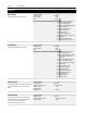
[Aux Input Select]
This parameter programs the action that occurs
when the “Auxiliary“ input is opened (low) and the
drive is running.
One of the following 5 actions may be selected:
0 Status only, no action. The drive continues to run,
but a status bit is available through remote I/O
communications to the programmable controller.
1 Drive continues to run, report status bit is sent to
the programmable controller and indicates alarm
status through the alarm contact CR4. Alarm will
be issued when TB2-16 & 17 opens and TB2-17
& 18 closes.
2 Drive ramps-to-stop, report status bit is sent to the
programmable controller and indicates fault status
through the fault contact CR3. When the input is
low (0), the drive will do a programmed ramp-to-
stop and display “Auxiliary Fault.”
3 Drive will coast-to-stop, report status bit is sent to
programmable controller and fault status is indi-
cated through fault contact CR3. When the input
is low (0), the drive will coast-to-stop and display
“Auxiliary Fault.”
4 DC injection brake-to-stop. Report status bit is
sent to the programmable controller and fault sta-
tus is indicated through the fault contact CR3.
When the input is low (0), the drive will brake-to-
stop using the value programmed for [DC Hold
Time] and [DC Hold Level]. During the hold time,
the drive cannot be reset or restarted until the
hold time is complete.
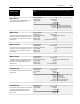
Parameter Number 174
Parameter Type Read and Write
Factory Default “0”
Units Display Drive
“0” 0
Status Only
“1” 1 Alarm
“2” 2 Fault/Ramp
“3” 3 Fault/Coast
“4” 4 Fault/Brake
Faults