
User Manual


2–16 Installation/Wiring
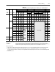
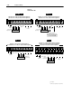
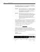
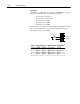
Figure 2.3
TB2 Connections
1
Analog Out
Contacts Shown
in Unpowered State
10k Ohm
4-20mA
to
TE
0-10V
Pulse
Source
Reserved for
Future Use
CR2
TETE
CR1
Logic
Common
Only Present
on B Frame
& Up Drives
Only Present
on B Frame
& Up Drives
CR3
Typical
CR3 CR4CR4
23456
9
10
11 12 13 14 15 16 17 18 A1 A287
User Supplied
Analog Device
– +– ++ +
3.42k
100
100 52.3k
100
215
215
75k
47.5k
150
1.4k
1µf
1µf
1µf
12 Bit
D/A
+5V
10 Bit
A/D
10 Bit
A/D
10 Bit
A/D
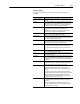
Table 2.E
Terminal Block TB2 Specifications
Terminal
Signal
TE True Earth – Shield Termination
1, 2, 3 External Speed Pot. or Analog Trim Pot. (10k ohm pot. required)
2
4 Signal Common
5 0-10V DC Input
2
Input Impedance = 100k ohms
6 4-20mA Input
2
Input Impedance = 250 ohms
7, 8 Pulse Input
4
Refer to Pulse Input on the following page
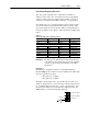
9 Analo
g
Output
1
Jumper JP1 to select 0-10V DC output
5
9
Analog
Out ut
A Frame Drives
Jum er
JP1
to
select
0-10V
DC
out ut
Jumper JP2 to select 0-20mA output
6
Analog Output
1
B Frame Drives and Up
Jumper J5 selects output
pins 1-2 = 0-20mA
6
pins 3-4 = 0-10V DC
5
10, 11 CR1 Programmable Contact
11 12
CR2 Run Contact
11, 12 CR2 Run Contact
13
,
14 CR3 Fault
Resistive Rating = 115V AC/30V DC, 5.0A
13
,
14
14, 15
CR3
Fault
CR3 Fault NOT Contact
3
Resistive
Rating
115V
AC/30V
DC,
5.0A
Inductive Rating = 115V AC/30V DC, 2.0A
16
,
17 CR4 Alarm
g 5 C/30 C, 0
16
,
17
17, 18
CR4
Alarm
CR4 Alarm NOT Contact
A1, A2 Reserved for Future Use