
User Manual


IndexI–2
UW Short Fault, 6–6
VW Short Fault, 6–6
Xsistr Desat Flt, 6–6
Filtering, RFI, 2–7, 2–8, C–3
Frame References, 1–1
Function Index, 5–1
Fusing, Input, 2–4
G
Grounding, 2–7
H
Human Interface Module (HIM)
Character Map, A–7
Description, 3–1
Key Descriptions, 3–2
Operation, 3–4
Removal, 3–15
I
Input Devices, 2–5
Input Mode Selection, 2–22
Input Power Conditioning, 2–4
Input/Output Rating, A–2
Interference, EMI/RFI, 2–6
Isolation Transformer, 2–4
L
L4/L4E Option, 2–24
L5/L5E Option, 2–25
L6/L6E Option, 2–26
Logic Control Structure, A–8
M
Min./Max. Frequency, 5–9
Motor Cable Length, 2–12
Motor Starting/Stopping, 2–5
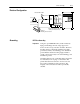
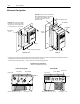
Mounting, 2–1
N
Nameplate Location, 1–3
O
Output Devices, 2–28
Overload, 5–10
P
Parameter Cross Ref.
By Name, A–6
By Number, A–5
Parameter Record, A–11
Parameters
% Output Curr, 5–7
% Output Power, 5–7
0-10 Volt Hertz, 5–6
4-20 mA Hertz, 5–6
4-20 mA Loss Sel, 5–15
Accel Mask, 5–37
Accel Owner, 5–39
Accel Time, 5–8, 5–15
Alarm Mask, 5–38
Analog Filter, 5–19
Analog Invert, 5–14
Analog Out Sel, 5–25
Analog Trim En, 5–14
Anlg Out Offset, 5–25
Application Sts, 5–35
Aux Input Select, 5–31
Base Frequency, 5–9, 5–12
Base Voltage, 5–9, 5–12
Blwn Fuse Flt, 5–27
Break Frequency, 5–12
Break Voltage, 5–12
Bus Limit En, 5–16
Clear Fault, 5–27
Cur Lim Trip En, 5–27
Current Angle, 5–34
Current Limit, 5–10
Current Lmt En, 5–10
Data In, 5–41
Data Out, 5–41
DC Boost Select, 5–13
DC Bus Memory, 5–35
DC Bus Voltage, 5–5
DC Hold Level, 5–16
DC Hold Time, 5–16
Decel Mask, 5–37
Decel Owner, 5–40
Decel Time, 5–9, 5–15
Dig Out Current, 5–25
Dig Out Freq, 5–25
Dig Out Torque, 5–25
Digital Out Sel, 5–25
Direction Mask, 5–37
Direction Owner, 5–39
Drive Alarm, 5–32
Drive Direction, 5–33
Drive Rtd Volts, 5–36
Drive Status, 5–32