
User Manual

2–5Installation/Wiring
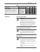
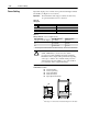
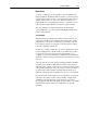
Table 2.A
Maximum Recommended AC Input Line Fuse Ratings (fuses are user supplied)
European Installations North American Installations
Drive Catalog
Number
kW (HP)
Rating
200-240
V Rating
380-480
V Rating
Recommended fuse is Class gG, general industrial applications
and motor circuitprotection
UL requirements specify that
UL Class CC T or J
1
fuses
1336S- _ _ F20 1.5 (2) 15A
2
10A
2
gg
and motor circuit protection.
BS88 (British Standard) Parts1&2
*
EN60269 1 Parts1&2
y
UL Class CC, T or J
1
fuses
must be used for all drives in
1336S- _ _ F50 3.7 (5) 40A
2
20A
2
BS88 (British Standard) Parts 1 & 2*, EN60269-1, Parts 1 & 2,
type gG or equivalent should be used for these drives. Fuses that
must
be
used
for
all
drives
in
this section*.
1336S- _ _ F100 7.5 (10) – 30A
2
ty e
gG
or
equivalent
should
be
used
for
these
drives
.
Fuses
that
meet BS88 Parts 1 & 2 are acceptable for Frames A - F.
*T i ld i ti i l d b t tb li itdt th fll i
* Typical designations include:
T CC KTK FNQ R
1336S- _ _ 010 7.5 (10) 50A 30A
*Typical designations include, but may not be limited to the following:
Parts1&2:AC AD BC BD CD DD ED EFS EFFFFG GF
Type CC: KTK, FNQ-R
T
y
pe J: JKS
,
LPJ
1336S- _ _ 015 11 (15) 70A 35A
P
ar
t
s
1
&
2
:
AC
,
AD
,
BC
,
BD
,
CD
,
DD
,
ED
,
EFS
,
EF
,
FF
,
FG
,
GF
,
GG, GH.
Ty e
J: JKS
,
LPJ
Type T: JJS, JJN
1336S- _ _ 030 22 (30) 125A 70A
1
Both fast acting and slow blow are acceptable.
2
Dual element-time delay fuses are required.
Starting and Stopping the Motor
!
ATTENTION: The drive start/stop control circuitry
includes solid-state components. If hazards due to
accidental contact with moving machinery or
unintentional flow of liquid, gas or solids exist, an
additional hardwired stop circuit may be required to
remove AC line power to the drive. When AC power is
removed, there will be a loss of inherent regenerative
braking effect & the motor will coast to a stop. An
auxiliary braking method may be required.
Repeated Application/Removal of Input Power
!
ATTENTION: The drive is intended to be controlled
by control input signals that will start and stop the
motor. A device that routinely disconnects then
reapplies line power to the drive for the purpose of
starting and stopping the motor is not recommended.
Bypass Contactors
!
ATTENTION: An incorrectly applied or installed by-
pass system can result in component damage or reduc-
tion in product life. The most common causes are:
• Wiring AC line to drive output or control terminals.
• Improper bypass or output circuits not approved by
Allen-Bradley.
• Output circuits which do not connect directly to the
motor.
Contact Allen-Bradley for assistance with application
or wiring.
Input Devices