336 PLUS Adjustable Frequency AC Drive for the Fiber Industry 1.
Important User Information Solid state equipment has operational characteristics differing from those of electromechanical equipment. “Safety Guidelines for the Application, Installation and Maintenance of Solid State Controls” (Publication SGI-1.1) describes some important differences between solid state equipment and hard–wired electromechanical devices.
Table of Contents Information and Precautions Chapter 1 Installation/Wiring Chapter 2 Manual Objectives . . . . . . . . . . . . . . . . . . . . . . . . . . . . . . . . . . . . Software Compatibility . . . . . . . . . . . . . . . . . . . . . . . . . . . . . . . . . Conventions Used in this Manual . . . . . . . . . . . . . . . . . . . . . . . . . General Precautions . . . . . . . . . . . . . . . . . . . . . . . . . . . . . . . . . . Catalog Number Explanation . . . . . . . . . . . . . . . . . . . . . . .
ii Table of Contents Troubleshooting Chapter 6 Fault Descriptions . . . . . . . . . . . . . . . . . . . . . . . . . . . . . . . . . . . . Alarms . . . . . . . . . . . . . . . . . . . . . . . . . . . . . . . . . . . . . . . . . . . . Specifications and Supplemental Information 6–1 6–8 Appendix A Specifications . . . . . . . . . . . . . . . . . . . . . . . . . . . . . . . . . . . . . . . User Supplied Enclosures . . . . . . . . . . . . . . . . . . . . . . . . . . . . . . Derating Guidelines . . . . . .
Chapter 1 Information and Precautions Chapter 1 provides general information on the 1336 PLUS Adjustable Frequency AC Drive for use in the Fiber Industry. Manual Objectives This publication provides planning, installation, wiring and diagnostic information. To assure successful installation and operation, the material presented must be thoroughly read and understood before proceeding. Particular attention must be directed to the Attention and Important statements contained within.
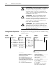
1–2 Information and Precautions ! ! ! Catalog Number Explanation ATTENTION: An incorrectly applied or installed drive can result in component damage or a reduction in product life. Wiring or application errors, such as, undersizing the motor, incorrect or inadequate AC supply, or excessive ambient temperatures may result in malfunction of the system.
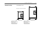
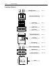
Information and Precautions Nameplate Location 1–3 1336 PLUS Nameplate Location 1 Refer to page 1-1 for frame reference classifications.
1–4 Information and Precautions End of Chapter
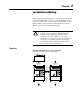
Chapter 2 Installation/Wiring Chapter 2 provides the information you need to properly mount and wire the 1336 PLUS Drive. Since most start-up difficulties are the result of incorrect wiring, every precaution must be taken to assure that the wiring is done as instructed. All items must be read and understood before the actual installation begins. ATTENTION: The following information is merely a guide for proper installation.
2–2 Installation/Wiring Installation Guidelines GND AC Supply Source Page 2–3 CAT. NO. FREQUENCY POWER RATING PRIMARY VOLTAGE SECONDARY VOLTAGE INSULATION CLASS NO. OF PHASES VENDOR PART NO.
Installation/Wiring AC Supply Source 2–3 1336 PLUS drives are suitable for use on a circuit capable of delivering up to a maximum of 200,000 rms symmetrical amperes, 600 volts maximum when used with the AC input line fuses specified in Table 2.A. ATTENTION: To guard against personal injury and/or equipment damage caused by improper fusing, use only the recommended line fuses specified in Table 2.A.
2–4 Installation/Wiring Input Power Conditioning In general, the 1336 PLUS is suitable for direct connection to a correct voltage AC line that has a minimum impedance of 1% (3% for 0.37-22 kW/0.5-30 HP drives) relative to the rated drive input kVA. If the line has a lower impedance, a line reactor or isolation transformer must be added before the drive to increase line impedance.
Installation/Wiring 2–5 Table 2.A Maximum Recommended AC Input Line Fuse Ratings (fuses are user supplied) European Installations North American Installations Recommended fuse is Class gG, g general g industrial applications and motor circuit protection protection. UL requirements specifyy that UL Class CC, CC T or J 1 fuses must be used for all drives in BS88 (British Standard) Parts 1 & 2 *, * EN60269 EN60269-1, 1 Parts 1 & 22, this section *. ty e gG or equivalent should be used for these drives.
2–6 Installation/Wiring Electrical Interference – EMI/RFI Immunity The immunity of 1336 PLUS drives to externally generated interference is good. Usually, no special precautions are required beyond the installation practices provided in this publication. It is recommended that the coils of DC energized contactors associated with drives be suppressed with a diode or similar device, since they can generate severe electrical transients.
Installation/Wiring RFI Filtering 2–7 1336 PLUS drives can be installed with an RFI filter, which controls radio-frequency conducted emissions into the main supply lines and ground wiring. If the cabling and installation recommendation precautions described in this manual are adhered to, it is unlikely that interference problems will occur when the drive is used with conventional industrial electronic circuits and systems.
2–8 Installation/Wiring Encoder & Communications Cabling If encoder connections or communications cables are used, the wiring must be separated from power cabling. This can be accomplished with carefully routed, shielded cable (ground cable shield at the drive end only) or a separate steel conduit (grounded at both ends). Belden 9730, 8777 (or equivalent) is recommended for encoder cable runs less than 30 meters (100 feet).
Installation/Wiring 2–9 General Grounding Common Mode Core* U (T1) Conduit/4-Wire Cable R (L1) ESC S (L2) Shield* V (T2) SEL JOG W (T3) PE/Gnd. T (L3) Shield Motor Frame PE Motor Terminator* RIO/DH+ or Analog Common Mode Core* Nearest Building Structure Steel PE Ground per Local Codes * Options that can be installed as needed.
Installation/Wiring Power Cabling Input and output power connections are performed through terminal block, TB1 (see Figure 2.1 for location). Important: For maintenance and setup procedures, the drive may be operated without a motor connected. Table 2.B TB1 Signals Description Potential Earth Ground AC Line Input Terminals DC Bus Terminals Motor Connection Terminal PE R (L1), S (L2), T (L3) +DC, –DC U (T1), V (T2), W (T3) Table 2.
Installation/Wiring 2–11 Motor Cables A variety of cable types are acceptable for drive installations. For many installations, unshielded cable is adequate, provided it can be separated from sensitive circuits. As an approximate guide, allow a spacing of 0.3 meters (1 foot) for every 10 meters (32.8 feet) of length. In all cases, long parallel runs must be avoided. Do not use cable with an insulation thickness less than or equal to 15 mils.
2–12 Installation/Wiring Conduit If metal conduit is preferred for cable distribution, the following guidelines must be followed. • Drives are normally mounted in cabinets and ground connections are made at a common ground point in the cabinet. Normal installation of conduit provides grounded connections to both the motor frame ground (junction box) and drive cabinet ground. These ground connections help minimize interference.
Installation/Wiring 2–13 Table 2.D Maximum Motor Cable Length Restrictions in meters (feet) – 380V-480V Drives 1 No External Devices Motor A B 1329 1329R, L Drive Frame Drive kW (HP) Motor kW (HP) Any Cable Any Cable Any Cable Any Cable A2 1.5 (2) 1.5 (2) 7.6 (25) 7.6 (25) 7.6 (25) 7.6 (25) 7.6 (25) 7.6 (25) 7.6 (25) 7.6 (25) 7.6 (25) 7.6 (25) 7.6 (25) 7.6 (25) 7.6 (25) 7.6 (25) 7.6 (25) 12.2 (40) 12.2 (40) 12.2 (40) 12.2 (40) 12.2 (40) 12.2 (40) 12.2 (40) 12.2 (40) 12.2 (40) 12.2 (40) 12.
2–14 Installation/Wiring Figure 2.2 Terminal Block TB1 A2-A3 Frame A4 Frame 200-240V, 0.37-3.7 kW (0.5-5 HP) Terminal Designations 380-480V, 0.37-3.7 kW (0.5-5 HP) Terminal Designations 380-480V, 5.5-7.5 kW (7.5-10 HP) Terminal Designations 500-600V, 0.75-3.
Installation/Wiring Control and Signal Wiring 2–15 Terminal Block TB2 TB2 is located at the bottom of the Main Control Board. 0.37-7.5 kW (0.5-10 HP) A Frame drives have 18 positions. Remaining frame sizes from 5.5 kW (7.5 HP) and up have 22 positions. The maximum and minimum wire size accepted by TB2 is 2.1 and 0.30 mm2 (14 and 22 AWG). Maximum torque for all terminals is 1.36 N-m (12 lb.-in.). Use Copper wire only. See Figures 2.1 and 2.3.
Installation/Wiring Figure 2.3 TB2 Connections 10 Bit A/D 10 Bit A/D 10 Bit A/D Typical 150 47.5k 1µf 52.3k 1µf 75k +5V TE TE 2 1.4k 100 3 4 5 – 6 + 7 + 8 – 10 9 + 11 4-20mA 10k Ohm CR4 CR4 12 13 14 15 16 17 18 Only Present on B Frame & Up Drives A1 A2 + 0-10V to TE CR3 CR3 215 CR1 CR2 100 1 100 1µf Logic Common Only Present on B Frame & Up Drives 12 Bit D/A 215 3.
Installation/Wiring 1 2 3 4 5 6 2–17 Refer to the Output Config group parameters for analog scaling. Refer to the [Maximum Speed] parameter on page 5–43. Refer to Chapter 6 for contact description. Not available if Encoder Feedback option is used. Minimum Load Impedance: A Frame drives = 3.5k ohms B Frame drives & Up = 1.5k ohms. Recommended load for all frames = 10k ohms.
2–18 Installation/Wiring The user inputs are connected to the option board through TB3 (see Figure 2.1 for location). The L4, L5 and L6 options each have nine control inputs. The function of each input must be selected through programming as explained later in this section. The L4E, L5E and L6E options are similar to L4, L5 and L6 with the addition of encoder feedback inputs. Refer to Figure 2.6 (a, b & c) for input impedance values.
Installation/Wiring 2–19 Available Inputs A variety of combinations made up of the following inputs are available. Input 1st/2nd Accel/Decel Auxiliary Digital Pot Up/Down Enable Local Control Reverse Run Forward/Reverse Speed Select 1, 2, 3 Start Stop Type Stop/Fault Reset Sync Traverse Description These inputs allow selection of the accel or decel time used by the drive. Required for Operation – this input is intended to fault the drive via external devices (i.e. motor thermoswitch, O.L.
Installation/Wiring The available combinations are shown in Figure 2.5. Programming the [Input Mode] parameter to one of the Input Mode numbers listed, will select that combination of input functions. Important: If a Control Interface Option is not installed, the [Input Mode] parameter must be set to 1 (default) and jumpers must be installed as shown in Figure 2.7. If the drive was shipped from the factory without the option, these jumpers will have been installed.
Installation/Wiring 2–21 Speed Select/Frequency Reference The drive speed command can be obtained from a number of different sources. The source is determined by drive programming and the condition of the Speed Select Inputs on TB3 (or reference select bits of command word if PLC controlled – see Appendix A). The default source for a command reference (all speed select inputs open) is the selection programmed in [Freq Select 1].
2–22 Installation/Wiring Example 2 Input Mode 7 – Application is to follow a local HIM unless a preset speed is selected. The drive is programmed as follows: – – – – – [Freq Select 1] = Adapter 1 [Freq Select 2] = Preset Freq 1 [Preset Freq 1] = 10 Hz. [Preset Freq 2] = 20 Hz. [Preset Freq 3] = 30 Hz. Contact operation for the speed select switch is described in the table below. Since Input Mode 7 does not offer a Speed Select 3 input, [Preset Freq 4-7] are not available.
Installation/Wiring 2–23 Figure 2.5 Input Mode Selection & Typical TB3 Connections Maintained 19 Status 20 Stop/Fault Reset 3 21 Common 22 Status 23 Status 24 Status 25 Common 26 Status 27 Status 28 Status 29 Common 30 Enable 3 [Input Mode] 2-6 Three-Wire Control with Single-Source Reversing 19 Start 20 Stop/Fault Reset 3 21 Common Mode See Figure 2.6 for Wiring Information Momentary See Figure 2.
Installation/Wiring Momentary Maintained See Figure 2.
Installation/Wiring 2–25 Figure 2.6 a Option L4/L4E Wiring Typical 0.1µf 0.1µf 10.7k 10.7k 100 Typical 681 Isolated +5V 5V JP4 470 0.1µf 12V 470 90.9 Isolated Ground A IGND 19 20 21 22 23 24 25 26 27 28 29 30 31 32 A 33 34 ENC 12V 35 ENC RET 36 TB3 Contacts shown are general, refer to Figure 2.5 for Input Mode selection and recommended contact types.
2–26 Installation/Wiring Figure 2.6 b Option L5/L5E Wiring 510 510 100 Typical 20k Typical 0.22µf 681 5V JP4 510 12V 1k 90.9 A 19 20 21 22 23 24 25 26 27 28 29 30 31 32 A 33 34 ENC 12V 35 ENC RET 36 TB3 Common User Supplied 24V AC/DC +24V Contacts shown are general, refer to Figure 2.5 for Input Mode selection and recommended contact types.
Installation/Wiring 2–27 Figure 2.6 c Option L6/L6E Wiring 100 100 20k Typical 0.15µf 100 Typical 0.22µf 0.33µf 681 5V 499k JP4 12V 49 90.9 A 19 20 21 22 23 24 25 26 27 28 29 30 31 32 A 33 34 ENC 12V 35 ENC RET 36 TB3 Common Fuse 115V AC Fuse User Supplied 115V AC Contacts shown are general, refer to Figure 2.5 for Input Mode selection and recommended contact types.
Installation/Wiring The interface board is jumper selectable to accept a 5V TTL or 12V DC square-wave with a minimum high state voltage of 3.0V DC (TTL) or 7.0V DC (12 volt encoder). Maximum low state voltage is 0.4V DC. Recommended wire – shielded, 0.750 mm2 (18 AWG), 305 m (1000 ft.) or less. Maximum input frequency is 125kHz. See Encoder & Communications Cabling on page 2–8. Figure 2.
Installation/Wiring Output Devices 2–29 Drive Output Disconnection ! ATTENTION: Any disconnecting means wired to drive output terminals U, V & W must be capable of disabling the drive if opened during drive operation. If opened during operation, the drive will continue to produce output voltage between U, V, W. An auxiliary contact must be used to simultaneously disable the drive.
2–30 Installation/Wiring Optional Output Reactor Bulletin 1321 Reactors listed in the 1336 PLUS-3.0 Price Sheet can be used for drive input and output. These reactors are specifically constructed to accommodate IGBT inverter applications with switching frequencies up to 20 kHz. They have a UL approved dielectric strength of 4000 volts, opposed to a normal rating of 2500 volts.
Installation/Wiring Interface Board Installation and Removal Important: If the Control Interface Board is being installed, Main Control Board jumpers at pins 3 & 4 and 17 & 18 of J4 (J7 on B Frame & up drives) must be removed and the proper [Input Mode] selected. If this board is removed, these jumpers must be reinstalled and the [Input Mode] parameter must be programmed to “1.” Figure 2.
2–32 Installation/Wiring Adapter Definitions Serial communication devices such as the Human Interface Module that are connected to the drive are identified by SCANport serial communications as Adapters. Depending on the drive and options ordered, a number of different adapters are available as shown in Figure 2.8. Figure 2.9 shows the maximum distance allowed between devices. Figure 2.
Chapter 3 Human Interface Module Chapter 3 describes the various controls and indicators found on the optional Human Interface Module (HIM). The material presented in this chapter must be understood to perform the start-up procedure in Chapter 4. HIM Description When the drive mounted HIM is supplied, it will be connected as Adapter 1 (see Adapter Definitions in Chapter 2) and visible from the front of the drive. The HIM can be divided into two sections; Display Panel and Control Panel.
3–2 Human Interface Module Figure 3.2 HIM Display Panel LCD Display Display Panel Key Descriptions Escape When pressed, the ESCape key will cause the programming system to go back one level in the menu tree. Select Pressing the SELect key alternately causes the top or bottom line of the display to become active. The flashing first character indicates which line is active. Increment/Decrement These keys are used to increment and decrement a value or scroll through different groups or parameters.
Human Interface Module 3–3 Figure 3.3 HIM Control Panel Digital Speed Control and Indicator (also available with Analog Speed Pot.) Control Panel Key Descriptions Start The Start key will initiate drive operation if no other control devices are sending a Stop command. This key can be disabled by the [Logic Mask] or [Start Mask]. Stop If the drive is running, pressing the Stop key will cause the drive to stop, using the selected stop mode.
3–4 Human Interface Module Control Panel Key Descriptions (Continued) Change Direction Pressing this key will cause the drive to ramp down to zero Hertz and then ramp up to set speed in the opposite direction. The appropriate Direction Indicator will illuminate to indicate the direction of motor rotation. Refer to [Logic Mask] and [Direction Mask]. Direction LEDs (Indicators) The appropriate LED will illuminate continuously to indicate the commanded direction of rotation.
Human Interface Module 3–5 Figure 3.4 Status Display From this display, pressing any one of the 5 Display Panel keys will cause “Choose Mode” to be displayed. Pressing the Increment or Decrement keys will allow different modes to be selected as described below and shown in Figure 3.5. Refer to the pages that follow for operation examples. Display When selected, the Display mode allows any of the parameters to be viewed. However, parameter modifications are not allowed.
3–6 Human Interface Module Figure 3.
Human Interface Module Program and Display Modes 1. The Display and Program modes allow access to the parameters for viewing or programming. A. From the Status Display, press Enter (or any key). “Choose Mode” will be shown. or B. Press the Increment (or Decrement) key to show “Program” (or “Display”). Choose Mode Display Choose Mode Program C. Press Enter. or D. Press the Increment (or Decrement) key until the desired group is displayed. Choose Group Metering E. Press Enter.
3–8 Human Interface Module Process Mode or 1. When selected, the Process mode will show a custom display consisting of information programmed with the Process Display group of parameters. A. Follow steps A-C on the preceding page to access the Program mode. Choose Mode Program B. Press the Increment/Decrement key until “Process Display” is shown. Press Enter. Choose Group Process Display C.
Human Interface Module EEProm Mode The EEProm mode is used to restore all settings to factory default values or upload/ download parameters between the HIM and drive (Series B HIM, Only). Reset Defaults 1. To restore factory defaults: A. From the Status Display, press Enter (or any key). “Choose Mode” will be displayed. B. Press the Increment (or Decrement) key until “EEProm” is displayed. If EEProm is not in the menu, programming is password protected. Refer to Password Mode later in this section.
3–10 Human Interface Module Drive –> HIM (continued) C. Press Enter. An informational display will be shown, indicating the drive type and firmware version. D. Press Enter to start the upload. The parameter number currently being uploaded will be displayed on line 1 of the HIM. Line 2 will indicate total progress. Press ESC to stop the upload. HIM –> Drive E. “COMPLETE” displayed on line 2 will indicate a successful upload. Press Enter. If “ERROR” is displayed, see Chapter 6. 3.
Human Interface Module Search Mode 1. The Search Mode is only available with a Series A (version 3.0) or Series B HIM. This mode allows you to search through the parameter list and display all parameters that are not at the factory default values. A. From the Status Display, press Enter (or any key). “Choose Mode” will be shown. B. Press the Increment (or Decrement) key until “Search” is displayed. or Choose Mode Display Choose Mode Search C. Press Enter.
3–12 Human Interface Module Control Status Mode (continued) 2. This menu provides a means to view the fault queue and clear it when desired. Fault Queue/Clear Faults A. From the Control Status menu, press the Increment (or Decrement) key until “Fault Queue” is displayed. or Control Status Fault Queue B. Press Enter. C. Press the Increment (or Decrement) key until “View Faults” is displayed. or D. Press Enter. The fault queue will be displayed.
Human Interface Module Password Mode or 1. The factory default password is 0 (which disables password protection). To change the password and enable password protection, perform the following steps. A. From the Status Display, press Enter (or any key). “Choose Mode” will be shown. Choose Mode Display B. Press the Increment (or Decrement) key until “Password” is displayed. Choose Mode Password C. Press Enter. or or or and D. Press the Increment (or Decrement) key until “Modify” is displayed.
3–14 Human Interface Module Password Mode (continued) Login to the Drive or 2. The Program/EEProm modes and the Control Logic/Clear Queue menus are now password protected and will not appear in the menu. To access these modes, perform the following steps. A. Press the Increment (or Decrement) key until “Password” is displayed. B. Press Enter. “Login” will be displayed. C. Press Enter, “Enter Password” will be displayed. or Logout from the Drive or Password Login Enter Password < 0> D.
Human Interface Module Module Removal 3–15 For handheld operation, the module can be removed and located up to 10 meters (33 feet) from the drive. Refer to Adapter Definitions in Chapter 2 for details. ! Important: ATTENTION: Some voltages present behind the drive front cover are at incoming line potential. To avoid an electric shock hazard, use extreme caution when removing/replacing the HIM.
3–16 Human Interface Module End of Chapter
Chapter 4 StartĆUp This chapter describes how you start-up the 1336 PLUS Drive. Included are typical adjustments and checks to assure proper operation. The information contained in previous chapters of this manual must be read and understood before proceeding. Important: The 1336 PLUS is designed so that start-up is simple and efficient. The programmable parameters are grouped logically so that most start-ups can be accomplished by adjusting parameters in only one group.
4–2 Start-Up Initial Operation – Motor Disconnected 1. Verify that AC line power at the disconnect device is within the rated value of the drive. If a Control Interface option (L4, L5, L6, L4E, L5E, L6E) is installed, verify that the control power to this board matches the board rating. 2. Remove and lock-out all incoming power to the drive including incoming AC power to terminals R, S and T (L1, L2 and L3) plus any separate control power for remote interface devices.
Start-Up Apply Power 7. Apply AC power and control voltages to the drive. The LCD Display should light and display a drive status of “Stopped” and an output frequency of “+0.00 Hz.” Stopped +0.00 Hz If the drive detects a fault, a brief statement relating to the fault will be shown on the display. Record this information, remove all power and correct the fault source before proceeding. Refer to Chapter 6 for fault descriptions. 8.
4–4 Start-Up Program Input Mode 9. If a Control Interface option is installed, it is important that the Input Mode recorded in Chapter 2 be programmed into the drive. Since the control inputs to this option are programmable, incorrect operation can occur if an improper mode is selected. The factory default input mode disables all inputs except Stop and Enable. Verify your control scheme against the information provided in Chapter 2 and program the [Input Mode] parameter as follows: A.
Start-Up 10. Set [Maximum Freq] and [Maximum Voltage] parameters to correct values (typically line voltage/frequency). Set [Base Voltage] and [Base Frequency] parameters to the motor nameplate values. or or A. From the Status Display, press the Enter key (or any key). “Choose Mode” will be displayed. Choose Mode EEProm B. Press the Increment (or Decrement) key until “Program” is displayed. Choose Mode Program C. Press Enter. Metering D. Press the Increment key until “Setup” is displayed.
4–6 Start-Up 11. Setting Frequency Command. A. From the Status Display, press the Enter key (or any key). “Choose Mode” will be displayed. Choose Mode Program B. Press the Increment key until “Display” is shown. Choose Mode Display C. Press Enter. Setup D. Press the Decrement key until “Metering” is displayed. E. Press Enter. F. Press the Increment key until “Freq Command” is displayed. or Output Voltage 0 Vlts Freq Command +0.00 Hz G.
Start-Up 13. Checking Direction. A. Initiate a Reverse command. Important: With [Direction Mask] set to the default value, the reverse command must be issued from the HIM or other adapter. If the reverse command is to be issued from TB3, [Direction Mask] must first be programmed to allow direction control from TB3. The drive will ramp to zero speed, then ramp to [Maximum Freq] in the opposite direction.
4–8 Start-Up 15. Jog Control & Stop Mode Check. Press & Hold Jog Key Release Jog Key A. With the drive reset, but not running, press and hold the Jog key on the Control Panel. The motor should accelerate to the frequency programmed by the [Jog Frequency] parameter and remain there until the Jog key is released. When released, the drive should execute a stop function using the programmed stop mode. Verify that the correct stop mode was initiated. At Speed –10.00 Hz Stopped –0.00 Hz 16.
Start-Up ATTENTION: To avoid a hazard of electric shock, verify that the voltage on the bus capacitors has discharged. Measure the DC bus voltage at the + & – terminals of TB1. The voltage must be zero. ! Reconnect Motor B. Reconnect motor leads & replace cover. 18. Check for Correct Motor Rotation. ATTENTION: In the following steps, rotation of the motor in an undesired direction can occur.
4–10 Start-Up Set Power-Up Display or Set Electronic Overload 19. With HIM software versions 2.02 & up, the power-up display (Status, Process or Password) can be programmed to appear when drive power is applied. Simply access the desired display and simultaneously press the Increment and Decrement keys. 20. Electronic overload protection is factory set to drive maximum. A. To properly set the electronic overload protection, program [Overload Amps] (Setup group) to the actual nameplate F.L.A. B.
Chapter 5 Programming Chapter 5 describes parameter information for the 1336 PLUS. Parameters are divided into 14 groups for ease of programming and operator access. Grouping replaces a sequentially numbered parameter list with functional parameter groups that increases operator efficiency and helps to reduce programming time. For most applications, this means simplicity at startup with minimum drive tuning.
5–2 Programming OPERATOR LEVEL Power-Up Mode & Status Display ESC or SEL or or or "Choose Mode" MODE LEVEL Display (Read Only) Process Program (Read and Write) Parameter Groups Process Display Parameter Groups GROUP LEVEL Wraps to Linear List Metering page 5-5 Output Current Output Voltage Output Power DC Bus Voltage Output Freq Freq Command 4-20 mA Hertz 0-10 Volt Hertz Pot Hertz Pulse/Enc Hertz Heatsink Temp Last Fault Torque Current Flux Current % Output Power % Output Curr PARAMETER L
Programming HIM Versions 2.02 & Up EEPROM Search Reset Defaults Drive -> HIM 1 HIM -> Drive 1 Recall Values 2 Save Values 2 HIM Versions 2.02 & Up Control Status Password Control Logic Fault Queue Login, Logout, Modify 1 Series B HIM Only.
5–4 Programming Chapter Conventions Parameter descriptions adhere to the following conventions. 1. All parameters required for any given drive function will be contained within a group, eliminating the need to change groups to complete a function. 2. All parameters are documented as either having ENUMS or Engineering Units. ENUMS [Parameter Name] Parameter description.
Programming Metering [Output Current] This parameter displays the output current present at TB1, terminals T1, T2 & T3 (U, V & W). [Output Voltage] This parameter displays the output voltage present at TB1, terminals T1, T2 & T3 (U, V & W). [Output Power] This parameter displays the output power present at TB1, terminals T1, T2 & T3 (U, V & W). [DC Bus Voltage] This parameter displays the DC bus voltage level.
5–6 Programming Metering [4-20 mA Hertz] This parameter displays the frequency command present at analog current input terminals 4 & 6 of TB2. This value is displayed whether or not this is the active frequency command. [0-10 Volt Hertz] This parameter displays the frequency command present at analog voltage input terminals 4 & 5 of TB2. This value is displayed whether or not this is the active frequency command.
Programming 5–7 Metering [Flux Current] This parameter displays the amount of current that is out of phase with the fundamental voltage component. It is the current required to maintain motor flux. [% Output Power] This parameter displays the % output power of the drive. [% Output Curr] This parameter displays the % output current of the drive. Parameter Number Parameter Type Display Units / Drive Units Factory Default Minimum Value Maximum Value 163 Read Only 0.
Programming This group of parameters defines basic operation and should be programmed before initial use of the drive. For advanced programming and information on specific parameters, refer to the flow chart on pages 5–2 & 5–3. Setup [Input Mode] This parameter selects the functions of inputs 1-8 at TB3 when an optional interface card is installed. Refer to Input Mode Selection figure in Chapter 2. This parameter cannot be changed while the drive is running.
Programming Setup [Decel Time 1] This value determines the time it will take the drive to ramp from [Maximum Freq] to 0 Hz. The rate determined by this value and [Maximum Freq] is linear unless [S Curve Enable] is “Enabled.” It applies to any decrease in command frequency unless [Decel Time 2] is selected. [Base Frequency] This value should be set to the motor nameplate rated frequency.
5–10 Programming Setup Parameter Number Parameter Type Factory Default Units [Stop Select 1] This parameter selects the stopping mode when the drive receives a valid stop command unless [Stop Select 2] is selected. 10 Read and Write “Coast” Display Drive “Coast” 0 Causes the drive to turn off immediately. “DC Brake” 1 Injects DC braking voltage into the motor. Requires a value in both [DC Hold Time] & [DC Hold Level].
Programming 5–11 Setup [Sync Time] The time it takes for the drive to change from the old frequency to the new frequency, once the Sync input is given. [Ride Thru Mode] Selects one of five methods to detect/respond to a line loss. Parameter Number Parameter Type Display Units / Drive Units Factory Default Minimum Value Maximum Value 22 Read and Write 0.1 Second / Seconds x 10 0.0 Sec 0.0 Sec 6000.
5–12 Programming Advanced Setup [Minimum Freq] This parameter sets the lowest frequency the drive will output. [Maximum Freq] This parameter sets the highest frequency the drive will output. This parameter cannot be changed while the drive is running. [Base Frequency] This value should be set to the motor nameplate rated frequency. [Base Voltage] This value should be set to the motor nameplate rated voltage. [Break Frequency] This parameter sets a midpoint frequency on a custom volts-per-Hertz curve.
Programming 5–13 Advanced Setup [DC Boost Select] This parameter sets the level of DC Boost that will be applied at low frequencies (typically 0-7 Hz). Auto settings automatically measure motor resistance and adjust the boost voltage to maintain constant boost performance regardless of changing motor temperature. This setting represents the amount of voltage required to produce the percent of drive rated current in a non-rotating motor (i.e. 45%).
5–14 Programming Advanced Setup [Run/Accel Boost] Sets the percentage of Auto Boost that is applied to the motor during constant speed or decel. If Auto Boost is selected in the [DC Boost Select] parameter (see preceding page), boost is applied as shown in the adjacent chart. [PWM Frequency] This parameter sets the carrier frequency for the sine coded PWM output waveform. This parameter cannot be changed while the drive is running.
Programming 5–15 Advanced Setup [4-20mA Loss Sel] This parameter selects the drives reaction to a loss of 4-20mA signal when the active [Freq Source] is 4-20mA. Parameter Number Parameter Type Factory Default Units 150 Read and Write “Min/Alarm” Display Drive “Min/Alarm” 0 Drive outputs [Minimum Freq] and issues an alarm. “Stop/Fault” 1 Drive stops and issues “Hertz Err Fault”. “Hold/Alarm” 2 Drive maintains last output freq and issues an alarm.
5–16 Programming Advanced Setup [DC Hold Time] This value sets the amount of time that the [DC Hold Level] voltage will be applied to the motor when the stop mode is set to either ”DC Brake” or “Ramp.” Parameter Number Parameter Type Display Units / Drive Units Factory Default Minimum Value Maximum Value 12 Read and Write 0.1 Second / Seconds x 10 0.0 Sec 0.
Programming 5–17 Advanced Setup [Stop Select 2] This parameter selects the stopping mode when the drive receives a valid stop command unless [Stop Select 1] is selected. Parameter Number Parameter Type Factory Default Units 52 Read and Write “Coast” Display Drive “Coast” 0 Causes the drive to turn off immediately. “DC Brake” 1 Injects DC braking voltage into the motor. Requires a value in both [DC Hold Time] & [DC Hold Level].
5–18 Programming This group of parameters contains internally stored frequency settings. Frequency Set [Freq Select 1] This parameter controls which of the frequency sources is currently supplying the [Freq Command] to the drive unless [Freq Select 2] or [Preset Freq 1-7] is selected. Refer to the Speed Select Input Table in Chapter 2.
Programming 5–19 Frequency Set Parameter Number(s) Parameter Type Display Units / Drive Units Factory Default Minimum Value Maximum Value 32-34 Read and Write 1 Hertz / Hertz 400 Hz 0 Hz 400 Hz This parameter determines the band width around a [Skip Frequency]. The actual band width is 2 x [Skip Freq Band] –– 1/2 the band above and 1/2 the band below the skip frequency.
5–20 Programming Feature Select [Dwell Frequency] This value sets the frequency that the drive will immediately output (no Accel Ramp) upon a start command. This parameter requires a programmed [Dwell Time]. [Dwell Time] This value sets the time the drive will continue to output [Dwell Frequency] before ramping to [Freq Command]. This group contains the necessary parameters to activate and program advanced features of the drive.
Programming Feature Select [Reset/Run Tries] This value sets the maximum number of times the drive attempts to reset a fault and restart before the drive issues a “Max Retries Fault”. See Chapter 6 for a list of resettable faults. [Reset/Run Time] This value sets the time between restart attempts when [Reset/Run Tries] is set to a value other than zero. [S Curve Enable] This parameter enables the fixed shape S curve accel/decel ramp.
5–22 Programming Feature Select [S Curve Time] This creates an adjustable s curve ramp. If S Curve Time is < the programmed accel/decel time, the actual ramp will be the sum of the two. If S Curve Time is ≥ the programmed accel/decel times, a fixed S curve will be created whose time is double the programmed accel/decel time. [Language] This parameter selects between English and the alternate language (not currently available) for the HIM display.
Programming 5–23 Feature Select [FStart Reverse] This value sets the frequency at which the reverse speed search begins. If this value exceeds [Maximum Freq], speed search will begin at [Maximum Freq]. Reverse search ends at zero Hertz or when motor speed is found. [Traverse Inc] This value sets the traverse increase time independently. See figure below. [Traverse Dec] This value sets the traverse decrease time independently. See figure below.
5–24 Programming Feature Select [P Jump] This value sets the slip or inertia compensation amplitude of speed modulation. [Sync Loss Sel] This parameter allows selection of various sync loss modes. The Sync Loss feature detects a synchronous motor that is out of sync. Parameter Number Parameter Type Display Units / Drive Units Factory Default Minimum Value Maximum Value Parameter Number Parameter Type Factory Default Units 80 Read and Write 0.01 Hertz / 32767 = [Maximum Freq] 0.00 Hz 0.
Programming Output Config [Digital Out Sel] This parameter sets the condition that closes the output contact at TB2 terminals 10 & 11. [Dig Out Freq] This value sets the trip point for the output contact at TB2 terminals 10 & 11 when [Digital Out Sel] is set to “At Frequency”. The contact will be closed when above this value. [Dig Out Current] This value sets the trip point for the output contact at TB2 terminals 10 & 11 when [Digital Out Sel] is set to “At Current”.
5–26 Programming Output Config Analog Out Offset Offset Maximum Speed Drive Output Frequency Minimum Frequency 0V 0 mA 2V 4 mA Analog Output Signal 10 V 20 mA
Programming 5–27 This group of parameters allows configuring, viewing and clearing drive faults. Faults [Fault Buffer 0-3] These parameters store the last (4) faults that occur. [Clear Fault] Selecting “Clear Fault” and pressing Enter will clear any faults and return the drive to ready status. [Cur Lim Trip En] This setting determines the drive response when the hardware current limit is exceeded.
5–28 Programming Faults Power Loss Ride-Thru The 1336 plus has the ability to ride through short power interruptions. On loss of input power to the drive, the drive offers two methods of operation. Diagram 1 With the Line Loss Fault parameter disabled, if a power interruption occurs (T1) the drive will continue to operate off stored DC bus energy until bus voltage drops to 85% of its nominal value (T2). At this point, the drive output is shut off, allowing the DC bus to discharge more slowly.
Programming 5–29 Faults [Flt Motor Mode] This parameter displays the motor mode active at the time of the last fault. [Flt Power Mode] This parameter displays the power mode active at the time of the last fault. These values can be helpful in troubleshooting for a condition causing a fault. [Fault Frequency] This parameter stores and displays the last [Output Freq] prior to a fault.
5–30 Programming Faults [Flt Driv Status] Parameter Number Parameter Type This parameter stores and displays the last [Drive Status] prior to a fault. Bits 0-7 are displayed on lower half of line 2 on HIM display, while, bits 8-15 are displayed on the upper half of line 2. With a Series A (version 3.0) or Series B HIM, a Status description (bit ENUM) is displayed on line 1. [Fault Alarms] This parameter stores and displays the last alarm conditions present prior to a fault.
Programming Faults [Aux Input Select] This parameter programs the action that occurs when the “Auxiliary“ input is opened (low) and the drive is running. One of the following 5 actions may be selected: 0 Status only, no action. The drive continues to run, but a status bit is available through remote I/O communications to the programmable controller. 1 Drive continues to run, report status bit is sent to the programmable controller and indicates alarm status through the alarm contact CR4.
5–32 Programming This group of parameters contains values that can be helpful in explaining the operation of the drive. Drive status, direction, control and alarm conditions as well as drive ratings are included. Diagnostics [Drive Status] This parameter displays the actual operating condition in binary format. Bits 0-7 are displayed on lower half of line 2 on HIM display, while, bits 8-15 are displayed on the upper half of line 2. With a Series A (version 3.
Programming 5–33 Diagnostics [Input Status] This parameter displays the on/off status of inputs 1-8 at TB3 if an optional interface card is installed. Parameter Number Parameter Type Bit 7 Bit 6 Bit 5 Bit 4 55 Read Only Bit 3 This parameter displays the frequency source currently commanding the drive. [Freq Command] This parameter displays the frequency that the drive is commanded to output. This command may come from any one of the frequency sources selected by [Freq Select 1] or [Freq Select 2].
5–34 Programming Diagnostics [Motor Mode] This parameter displays the motor mode. [Power Mode] This parameter displays the power mode.
Programming 5–35 Diagnostics [Heatsink Temp] This parameter displays the heatsink temperature. [Set Defaults] Setting this parameter to “Defaults Init” resets all parameters to their factory values. Parameter Number Parameter Type Display Units / Drive Units Factory Default Minimum Value Maximum Value Parameter Number Parameter Type Factory Default Units This parameter cannot be changed while the drive is running. 70 Read Only 1° C / Deg.
5–36 Programming Ratings [Drive Type] This parameter displays a decimal number which can be translated into the drive catalog number by using the adjacent chart. Refer to Chapter 1 for an explanation of the catalog numbers. [Firmware Ver.] This parameter displays the version number of the drive firmware. [Drive Rtd Volts] This parameter displays the rated input voltage of the drive. [Rated Amps] This parameter displays the rated output current of the drive.
Programming Masks Each mask contains a bit for each adapter. Individual bits can be set to “Zero” to lockout control by an adapter or set to “1” to permit an adapter to have control. This group of parameters contains binary masks for all control functions. The masks control which adapters can issue control commands. Mask Bit 7 Bit 6 Not Used With a Series A (version 3.0) or Series B HIM, a Status description (bit ENUM) is displayed on line 1.
5–38 Programming Masks [Fault Mask] This parameter controls which adapters can reset a fault. [Sync Mask] This parameter controls and chooses which adapters can select the Sync function. [Traverse Mask] This parameter controls and chooses which adapters can select the Traverse function. [Logic Mask] Determines which adapters can control the drive. If the bit for an adapter is set to “0,” the adapter will have no control functions except for stop.
Programming Owners Each Owner Parameter contains a bit for each adapter. The drive will set an adapter’s bit to “1” when that adapter is issuing a logic command and to “Zero” when no command is being issued. This group of parameters contains binary information to display which group of adapters are issuing control commands. Owners Display Bit 7 Bit 6 Bit 5 Bit 4 Bit 3 Bit 2 Bit 1 Bit 0 TB3 Adapter 1 Adapter 2 Adapter 3 Adapter 4 Adapter 5 Adapter 6 Not Used With a Series A (version 3.
5–40 Programming Owners [Decel Owner] This parameter displays which adapter has exclusive control of selecting [Decel Time 1] or [Decel Time 2]. [Fault Owner] This parameter displays which adapter is presently resetting a fault. [Sync Owner] This parameter displays which adapters have exclusive control of selecting the Sync function. [Traverse Owner] This parameter displays which adapters have exclusive control of selecting the Traverse function.
Programming 5–41 This group of parameters contains the parameters needed for an optional communications adapter to communicate with the drive. Adapter I/O These parameters determine the parameter number to which PLC output data table or SCANport device image information will be written. Refer to the A-B Single Point Remote I/O Adapter manuals or other SCANport device manual for data link information.
5–42 Programming Process Display [Process 1 Par] This parameter should be set to the number of the parameter whose scaled value will be displayed on Line 1 of the HIM Display Panel. This group of parameters contains the parameters used to scale, in “User Units”, any drive parameter for display on the HIM. Two scaled parameter values can be simultaneously displayed when Process Mode is selected.
Programming Encoder Feedback [Speed Control] This parameter selects the type of speed modulation active in the drive. This group of parameters contains all the parameters necessary to activate encoder feedback for closed loop operation.
5–44 Programming Encoder Feedback [Speed KI] This parameter contains the integral gain value for the velocity loop during closed loop operation. [Speed Error] This parameter displays the difference between [Freq Command] and feedback speed. [Speed Integral] This parameter displays the integral value from the speed loop. [Speed Adder] This parameter displays the amount of correction applied to the [Freq Command]. [Motor NP RPM] This value should be set to the motor nameplate rated RPM.
Programming Linear List 5–45 This group lists all the parameters currently installed in your drive in numerical order. Refer to the Appendix at the back of this manual for an alpha/numeric listing of all parameters.
5–46 Programming End of Chapter
Chapter 6 Troubleshooting Chapter 6 provides information to guide the user in troubleshooting the 1336 PLUS. Included is a listing and description of the various drive faults (with possible solutions, when applicable) and alarms. Fault Descriptions Fault Display The LCD display is used to indicate a fault by showing a brief text statement relating to the fault (see figure below). The fault will be displayed until “Clear Faults” is initiated or drive power is cycled. A Series A (version 3.
6–2 Troubleshooting Table 6.A 1336 PLUS Fault Descriptions Name & Fault # Adptr Freq Err 65 Description The SCANport adapter that was the selected frequency reference sent a frequency greater than 32767 to the drive. Action Correct the problem that is causing the SCANport adapter to send the illegal frequency reference to the drive. Auxiliary Fault 02 The auxiliary input interlock is open. BGND 10ms Over 51 Microprocessor loop fault. Occurs if the 10ms background task hasn’t been run in 15 ms.
Troubleshooting 6–3 Name & Fault # Ground Fault 13 Description A current path to earth ground in excess of 100A has been detected at one or more of the drive output terminals. NOTE: If ground current exceeds 220% of drive rated current, “Overcurrent Flt” may occur instead of Ground Fault. Action Check the motor and external wiring to the drive output terminals for a grounded condition.
6–4 Troubleshooting Name & Fault # Motor Stall Fault 06 Description Current remained over 150% of [Rated Amps] for more than 4 seconds. Neg Slope Fault 35 Drive software detected a portion of the volts/hertz curve with a negative slope. Open Pot Fault 09 An external pot is connected and the common side of the pot is open. The drive generates this fault when the voltage between TB2-2 and TB2-3 exceeds 3.9V DC. A SCANport device requests a Read or Write of a data type not supported.
Troubleshooting 6–5 Name & Fault # P Jump Err Flt 37 Poles Calc Flt 50 Description Reserved for future use. Action Generated if the calculated value of [Motor Poles] is less than 2 or greater than 32. Check [Motor NP RPM] and [Motor NP Hertz] programming. Power Loss Fault 03 DC bus voltage remained below 85% (50% on A Frame drives) of nominal for longer than 500ms. [Line Loss Fault] parameter is set to “enabled.” Monitor the incoming AC line for low voltage or line power interruption.
6–6 Troubleshooting Name & Fault # Serial Fault 10 Description A SCANport adapter has been disconnected and the [Logic Mask] bit for that adapter is set to “1.” Sync Loss Fault 67 Temp Sense Open 55 Undervolt Fault 04 Synchronous motor pulled out of sync. Heat sink thermistor is open or malfunctioning. DC Bus voltage fell below the minimum value (388V DC at 460V AC input). [Line Loss Fault] and [Low Bus Fault] set to “enabled.
Troubleshooting Table 6.
6–8 Alarms Troubleshooting Table 6.C presents a listing and description of the drive alarms. Alarm status can be viewed by selecting the [Drive Alarm] parameter. An active alarm will be indicated by its corresponding bit being set to high (1). Any high bit (1) will energize CR4 (see figure 2.3).
A Appendix Specifications and Supplemental Information Appendix A provides specifications and supplemental information including a parameter cross reference and derate information. Protection AC Input Overvoltage Trip: AC Input Undervoltage Trip: Bus Overvoltage Trip: Bus Undervoltage Trip: Nominal Bus Voltage: 200-240V Drive 285V AC 138V AC 405V DC 200V DC 324V DC 380-480V Drive 570V AC 280V AC 810V DC 400V DC 648V DC Heat Sink Thermistor: Monitored by microprocessor overtemp trip.
A–2 Specifications and Supplemental Information Electrical Input Data Voltage Tolerance: Frequency Tolerance: Input Phases: –10% of minimum, +10% of maximum. 48-62 Hz. Three-phase input provides full rating for all drives. Single-phase operation is possible for A & B Frame drives at a derating of 50%. Displacement Power Factor A1-A3 Frame Drives: A4 Frame & Up Drives: 0.80 standard, 0.95 with optional inductor. 0.95 standard. Efficiency: 97.5% at rated amps, nominal line volts. Max.
Specifications and Supplemental Information User Supplied Enclosures A–3 1336 plus drives installed in user supplied enclosures may be mounted within an enclosure or may be mounted to allow the heat sink to extend outside the enclosure. Use the information below in combination with the enclosure manufacturer’s guidelines for sizing. Base Derate Cat No. Amps 1 200-240V DRIVES AQF20 8.0 AQF50 18 A015 48 380-480V DRIVES BRF50 9.0 BRF100 25.
A–4 Specifications and Supplemental Information ALTITUDE 100% Figure C All Drive Ratings % of Drive Rated Amps 90% 80% 0 1,000 (3,300) 2,000 (6,600) 3,000 (9,900) 4,000 (13,200) m (ft) Altitude HIGH INPUT VOLTAGE Figure D Required Only for the following drives: 100% 1336S-x030 – 22 kW (30 HP) at 6 or 8 kHz % of Drive Rated Amps 90% 80% 240, 480 or 600V Nominal +2% +4% +6% Input Voltage +8% +10%
Specifications and Supplemental Information A–5 Parameter Cross Reference – By Number No.
A–6 Specifications and Supplemental Information Parameter Cross Reference – By Name Name % Output Curr % Output Power 0–10 Volt Hertz 4–20 mA Loss Sel 4–20 mA Hertz Accel Mask Accel Owner Accel Time 1 Accel Time 2 Alarm Mask Analog Filter Analog Invert Analog Out Sel Analog Trim En Anlg Out Offset Application Sts Aux Input Select Base Frequency Base Voltage Blwn Fuse Flt Break Frequency Break Voltage Bus Limit En Clear Fault Common Bus Cur Lim Trip En Current Angle Current Limit Current Lmt En Data In A1
Specifications and Supplemental Information A–7 HIM Character Map Character ! " # $ % & ’ ( ) * + , .
A–8 Specifications and Supplemental Information Communications Data Information Format Drive Status Structure This provides the drive status information that will be sent to the logic controllers input image table when the Communication Module is set to control the drive. Logic Control Structure This information provides the control logic information that is sent to the drive through the logic controllers output image table when the Communication Module is set to control the drive.
Specifications and Supplemental Information Typical Programmable Controller Communications Configurations A–9 Using Datalink A1 Programmable Controller I/O Image Table Remote I/O Communication Module 1336 PLUS Adjustable Frequency AC Drive Output Image Block Transfer Logic Command Analog Reference WORD 3 WORD 4 WORD 5 WORD 6 WORD 7 Datalink A Parameter/Number Data In A1 Data In A2 111 112 Datalink A Data Out A1 119 Data Out A2 120 Input Image Block Transfer Logic Status Analog Feedback WORD 3 WOR
A–10 Specifications and Supplemental Information Typical Serial Communications Configurations Master Device Register Objects Serial to SCANport Communications Module 1336 PLUS Adjustable Frequency AC Drive Output Output WORD 1 WORD 2 WORD 1 WORD 2 WORD 3 WORD 4 WORD a WORD a+1 WORD 5 WORD 6 WORD b WORD b+1 WORD 7 WORD 8 WORD c WORD c+1 WORD 9 WORD 10 WORD d WORD d+1 Input Input WORD 1 WORD 2 WORD 1 WORD 2 WORD 3 WORD 4 WORD a WORD a+1 Datalink A WORD 5 WORD 6 WORD b WORD b+1 Datal
Specifications and Supplemental Information Read/Write Parameter Record No.
A–12 Specifications and Supplemental Information End of Chapter
Appendix B Dimensions Appendix B provides detailed dimension information for the 1336 PLUS. Included are: • IP 20 (NEMA Type 1) Dimensions. • Heat Sink-through-the-Back Cutout Dimensions. Important: The dimensions given on the following drawings are for estimating purposes only. Contact your Allen-Bradley Sales Office if certified drawings are required.
B–2 Dimensions IP 20 (NEMA Type 1) Dimensions – Frames A2 through A4 A Y Z C Max. D AA E B Mounting Hole Detail 7.0 (0.28) 7.0 (0.28) 12.7 (0.50) BB 12.7 (0.50) CC Mounting Holes (4) – See Detail Bottom View Will Vary with HP – See Bottom View Dimensions Three-Phase Rating 1, 2 380-480V 200-240V 1.5-2.2 kW 1.2-1.5 kW 2-3 HP 1.5-2 HP 3.7 kW 2.2-3.7 kW 5 HP 3-5 HP 5.5-7.5 kW * – 7.5-10 HP 5.5-22 kW * 5.5-11 kW 7.5-30 HP 7.
Dimensions B–3 IP 20 (NEMA Type 1) Dimensions – Frames B1/B2 A Y Z C Max. D Mounting Hole Detail (Frames B & C) 7.1 (0.28) 7.1 (0.28) 12.7 (0.50) 12.7 (0.50) AA E B Mounting Hole Detail (Frame D) BB R 5.2 (0.20) 14.7 (0.58) R 9.5 (0.38) CC Mounting Holes (4) – See Detail Bottom View Will Vary with HP – See Bottom View Dimensions All Dimensions in Millimeters and (Inches) All Weights in Kilograms and (Pounds) Frame Reference B1/B2 A 276.4 (10.88) B 476.3 (18.75) C Max. 225.0 (8.86) D 212.6 (8.
B–4 Dimensions IP 20 (NEMA Type 1) Bottom View Dimensions Frames A2 through A4 S R Q 22.2 (0.88) Conduit Knockout - 1 Plc. P 22.2/28.6 (0.88/1.13) Conduit Knockout - 3 Plcs. N M L Fans will be present on A4 Frame Frame Reference A2 A3 A4 L 132.3 (5.21) 158.8 (6.25) 164.0 (6.45) M 126.0 (4.96) 152.4 (6.00) 164.0 (6.45) N 106.9 (4.21) 133.4 (5.25) 139.0 (5.47) P 31.0 (1.22) 31.0 (1.22) 27.0 (1.06) Q 69.1 (2.72) 69.1 (2.72) 65.0 (2.56) R 102.1 (4.02) 102.1 (4.02) 97.0 (3.82) S 135.4 (5.33) 135.
Dimensions B–5 Heat Sink Through-the-Back Mounting – Frames A2 through A3 210.0 1 (8.25) 98.0 (3.86) 196.0 (7.72) 182.1 (7.17) 78.1 (3.076) 234.2 (9.2204) 249.7 1 (9.83) 78.2 (3.080) 220.0 (8.66) Cutout All Dimensions in Millimeters and (Inches) 10 Required 4.3 (0.171) Dia. for 10/32 Taptite® (or equiv.) – 4.0 (0.159) for 10/32 threaded Back of Enclosure Drive A1 = 50.8 (2.00) A2 = 71.4 (2.81) A3 = 98.8 (3.85) 1 Shading indicates approximate size of drive inside enclosure.
B–6 Dimensions Heat Sink Through-the-Back Mounting – Frame A4 257.0 1 (10.12) 80.4 (3.17) 160.9 (6.33) 120.7 (4.75) 241.3 (9.50) 225.0 (8.86) 301.2 (11.86) 225.9 (8.89) 317.0 1 (12.48) 285.0 (11.22) Cutout 150.6 (5.93) 75.3 (2.96) All Dimensions in Millimeters and (Inches) 14 Required 4.3 (0.171) Dia. for 10/32 Taptite® (or equiv.) – 4.0 (0.159) for 10/32 threaded Back of Enclosure Drive 90.0 (3.54) 1 Shading indicates approximate size of drive inside enclosure.
Dimensions B–7 Heat Sink Through-the-Back Mounting – Frame B1/B2 267.2 1 (10.52) 257.1 (10.12) 6.35 (0.25) 244.4 (9.62) 2.54 (0.10) 435.4 1 (17.14) 415.3 (16.35) 410.2 (16.15) 308.6 (12.15) Cutout as Viewed from INSIDE Enclosure 283.2 (11.15) 127.0 (5.00) All Dimensions in Millimeters and (Inches) 8 Required 4.3 (0.171) Dia. for 10/32 Taptite® (or equiv.) – 4.0 (0.159) for 10/32 threaded Drive Back of Enclosure 129.3 (5.09) 1 Shading indicates approximate size of drive inside enclosure.
B–8 Dimensions End of Chapter
Appendix C CE Conformity Low Voltage Directive The following low voltage directives apply: • EN 60204-1 • PREN 50178 EMC Directive This apparatus is tested to meet Council Directive 89/336 Electromagnetic Compatibility (EMC) using a technical construction file and the following standards: • EN 50081–1, –2 – Generic Emission Standard • EN 50082–1, –2 – Generic Immunity Standard Declarations of Conformity to the European Union Directives are available.
C–2 Filter CE Conformity Filter Selection Filter Catalog Number 1336-RFB-16-A 1336 RFB 16 A 1336-RFB-30-A 1336 RFB 30 A 1336-RFB-27-B 1336 RFB 27 B 1336-RFB-48-B 1336 RFB 48 B Three-Phase Volts 200-240V 380-480V 200-240V 380-480V 200-240V 380-480V 200-240V 380-480V Used with . . .
CE Conformity C–3 Electrical Configuration Conduit/4-Wire Cable R (L1) RFI Filter S (L2) ESC SEL JOG T (L3) PE Shield Terminated in Cable Clamp on A Frame Drives Nearest Building Structure Steel Grounding RFI Filter Grounding Important: Using the optional RFI filter may result in relatively high ground leakage currents. Surge suppression devices are also incorporated into the filter.
C–4 CE Conformity Mechanical Configuration Important: A positive electrical bond must be maintained between drive and filter at all 4 corners. Star washers can be eliminated if a positive electrical bond is assured. Three-Phase Input 1 Important: Drive and filter must be mounted to a common back plane with a positive electrical bond and in close proximity to one another.
Index A Encoder Wiring, 2–26 AC Supply Source, 2–3 Engineering Unit, 5–4 Adapter Definitions, 2–31 ENUM, 5–4 Alarms, 6–8 Analog Invert, 5–14 Auto Restart, 5–20 B Bypass Contactors, 2–5 C Cable Termination, 2–28 Catalog Number Explanation, 1–2 CE Conformity, 2–7, C–1 Common Mode Cores, 2–28 Contacts, Fault, 6–1 Control Interface Option Board Removal/Installation, 2–30 L4/L4E, 2–24 L5/L5E, 2–25 L6/L6E, 2–26 TB3 Description, 2–19 Control Status Mode, 3–5 D DC Brake to Stop, 5–16 Derate Guidelines, A–3
I–2 Index UW Short Fault, 6–6 VW Short Fault, 6–6 Xsistr Desat Flt, 6–6 Filtering, RFI, 2–7, 2–8, C–3 Overload, 5–10 P Function Index, 5–1 Parameter Cross Ref.
Index Drive Type, 5–36 Dwell Frequency, 5–20 Dwell Time, 5–20 Enable Output, 5–24 Encoder Type, 5–43 Fault Alarms, 5–30 Fault Buffer, 5–27 Fault Frequency, 5–29 Fault Mask, 5–38 Fault Owner, 5–40 Firmware Ver.
I–4 Index Preset Frequency, 5–18 Startup Procedure, 4–1 Process Mode, 3–5 Status Display, 3–5 Program Mode, 3–5 Programmable Controller Config., A–9 Programming Flow Chart, 5–1 T Reactors, 2–4 Terminal Blocks Locations, 2–10 TB1, 2–10 TB2, 2–16 TB3, 2–19 TB4/TB6, 2–29 Remote I/O, 5–41 Traverse Function, 5–23 Reset Defaults, 4–3 Troubleshooting Clearing a Fault, 6–1 Fault Code Cross Ref.
Publication 1336G-5.0 – May, 1997 Supersedes June, 1995 P/N 74002-068-01 (01) Copyright 1997 Allen-Bradley Company, Inc.