
User Manual

Wiring
Chapter 6
6-17
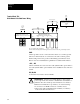
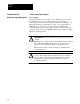
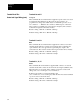
Terminal Block TB2 The drive is capable of operating from an optional Local or Remote
Control and Signal Wiring Control Panel with minimum connections to terminal block TB2. When
required, external operator elements may be connected to provide
additional drive control. Additional drive control functions and status
outputs are also available for use at TB2 as detailed on the following pages.
Pot
1 2 3 4 5 6 7 8 9 10 11 12 13 14 15 16 17 18
Wiper
Pot
High
Pot
Low
External
Speed Pot
+–
+–
+–
+–
CR1 CR2 CR3 CR3 CR4 CR4
ISOL
Analog
Meter
0–10V
Pulse
Source
4–20mA
At Fault (Not) Drive (Not)Run
Speed Fault Alarm Drive
Alarm
Shield
To
Pulse Input
From
D/A
To
A/D
2
To
A/D
3
To
A/D
1
+5V
DC
1.4kΩ
215Ω215Ω
100Ω
100Ω
47.5kΩ
200Ω
49.9Ω
53.3kΩ
75kΩ
100Ω
3.42kΩ
Chassis
Ground
Signal
Commo
n
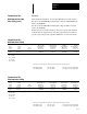
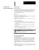
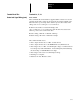
Maximum Recommended
Signal Wire Group ❶ Wire Size ❷ Torque ❸
Terminals 1, 2, 3 External Speed Potentiometer 5 14 AWG 7 In-Lbs
Terminals 3 and 4 Signal Common 5 14 AWG 7 In-Lbs
Terminals 5, Signal Common 0-10V DC 5 14 AWG 7 In-Lbs
Terminals 6, Signal Common 4-20mA 5 14 AWG 7 In-Lbs
Terminals 7 and 8 Pulse Train 6 14 AWG 7 In-Lbs
Terminals 9, Signal Common Meter Output 5 14 AWG 7 In-Lbs
Terminals 10 and 11 At Speed Contact 3 14 AWG 7 In-Lbs
Terminals 11 and 12 Run Contact 3 14 AWG 7 In-Lbs
Terminals 13, 14, 15 Fault Contacts 3 14 AWG 7 In-Lbs
Terminals 16, 17, 18 Drive Alarm Contacts 3 14 AWG 7 In-Lbs
❶
W
ire group number chart, page 6-3.
❷ 2.50 mm
2
.
❸ .79 N-m.