
User Manual

Wiring
Chapter 6
6-6
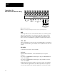
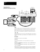
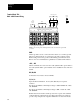
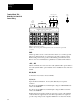
Terminal Block TB1 -
B003B030 & C003C030 Power Wiring
AC Incoming Line
GND GND +DC –DC M1 M2 M3 L1 L2 L3
Motor
∅A
∅A
USE 75°C COPPER WIRE ONLY WIRE RANGE 6–14 AWG
TIGHTENING TORQUE 20 INCH POUNDS
∅B ∅C
∅B ∅C
❶❶❶
❷
Earth
Ground
1336
Dynamic Brake
❶ User supplied drive input fuses.
❷ Motor disconnecting means including branch circuit, short circuit, and ground fault protection.
GND
Chassis ground is used to connect the drive chassis to a common ground.
The motor frame must also be connected to the same common ground.
Either earth ground or the ground of the building system must be used.
Refer to the motor manufacturer’s guidelines for additional information.
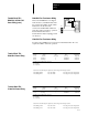
+ DC, - DC
DC bus terminals are reserved for the 1336 dynamic brake option. Refer to
the 1336 dynamic brake option instructions for installation and connection
details.
M1, M2, M3
Connect the motor leads to these terminals.
L1, L2, L3
Input AC line Terminals L1, L2, L3 (∅A, ∅B, ∅C) are not phase
sensitive.
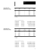
For drives rated B003-B030, nominal input voltage is 380/415/460V AC
±10%, 3∅, 50/60Hz.
For drives rated C003-C030, nominal input voltage is 500 or 575V AC
±10%, 3∅, 50/60Hz.
Branch disconnect and short circuit protection is not part of the standard
1336 and must be supplied by the user. Drive input fuses are required to
provide component protection against malfunction of electronic circuits.